Desperado
Veteran Member
- Joined
- Nov 25, 2017
- Messages
- 6,827
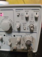
ALT/CHOP is IN now....Can you post a link to the oscilloscope manual again please?
Is the ALT/CHOP button IN or OUT?
Dave
There isn't any manual online...
Need i buy a new digital scope

ALT/CHOP is IN now....Can you post a link to the oscilloscope manual again please?
Is the ALT/CHOP button IN or OUT?
Dave
is now OUTAnd TRIG.ALT button. IN or OUT?
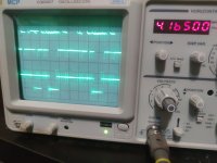
Honestly, these traces are making me feel like I’ve been taking crazy pills. If I had any compatible ROMs at hand I’d be tempted to make a NOP ROM for my PET and see if I could get a decent trace off it, because this still feels like something is wrong with the triggering here. Putting the trigger on the highest address line *should* give you a reliable timebase; that is a reference that will complete a full cycle once per iteration, and regardless of whether you triggered on the high or low slope the instructions following that transition will consistently be 2-cycle NOPs. (Over 4000 of them after each transition.)
I chucked out the idea earlier of building a single-stepper, that’s sounding less dumb to me.
You're right Dave, I don't think I can fix it. What I regret the most is that before deleting the EPROMs, it worked...Unfortunately you don't know whether it is the chicken or the egg...
If the CPU is faulty it will probably not execute the NOP EPROM correctly.
If the NOP EPROM is faulty, the CPU will not receive valid instructions.
Both the CPU and NOP EPROM could also be perfectly OK - and it is something else (a faulty or marginal piece of hardware) that is causing the problem.
I think this fault is currently way outside of your sphere of knowledge and test equipment to tackle.
I would have got out a very expensive piece of HP logic analyser by now and instrumented up the CPU with a whole load of probes to see exactly what it was doing on start-up.
An oscilloscope is not the piece of test equipment of choice for this fault I am afraid.
You have to know when to stop...
Dave
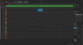
I believe what is messing up the expected regular pattern on the address signals is the DRAM refresh. If I understand the schematics on page 3 correctly, after each 20 clock cycles the CPU is halted for a refresh cycle by pulling the RDY line low.