• Please review our updated Terms and Rules here

Classic PDP-8 Donation at the RICM

m_thompson

Veteran Member
Joined
Jul 8, 2014
Messages
2,227
Location
Rhode Island, USA
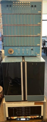
The Rhode Island Computer Museum just received a Classic or Straight PDP-8 and DEC Lab System donation from Sonny Monnosson's Boston Financial and Equity Corporation. It has an American Used Computer inventory tag on the back. The tale is that Sonny received a PDP-10 as partial payment for consulting services, and started American Used Computer to sell it. I will post more pictures after an complete inventory of the Flipchips.
1716383390609.png
 
Nice! The lab setup looks quite similar to the one I recently acquired and am attempting to restore.

I have an H903 in mine, but I can't find any information about which flip-chip it is supposed to contain. The description also doesn't match any module I am aware of. If you have any info about that, it would be great.

The straight-8 looks like fun too!
 
Nice! The lab setup looks quite similar to the one I recently acquired and am attempting to restore.

I have an H903 in mine, but I can't find any information about which flip-chip it is supposed to contain. The description also doesn't match any module I am aware of. If you have any info about that, it would be great.

Ours has a H902 indicator Switch Panel at the top. The lamp driver FlipChip is not installed and I don't know what it should be. Maybe a W052?

Any idea how to get or make the DEC Type 911 Banana-Jack Patch Cords?
 
I did some more investigating on the PDP-8 this afternoon. Doug reminded me that there are early and late versions of the Maintenance Manual, and they have some design changes. Since this is S/N 13 it is probably an early version.

There are a bunch of empty slots because the #183 Memory Extension Control and #188 Memory Parity options are not installed.
The FlipChips in slots MA30 through MA25 match the F-87 manual.
MB31 through MB25 match the F-87 manual.
MC31 through MC06 match the F-87 manual except that it has a B684 in slot C19 instead of a B602.
MD30 through MD06 match the F-87 manual except that it has G203B Memory Selectors instead of G209.
It looks like a G209 is an upgraded replacement for a G203.
ME28 through ME14 match the F-87 manual.
MF28 through MF15 match the F-87 manual.

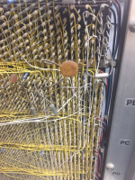
There is an R405 in MF29 and an R303 in ME29 that is not in the F-87 manual. There are a bunch of white wires going to the R303 in slot ME29. There is one white wire going to Pin D of the M405 in MF29. There are three wires that go from the slot ME29 to the Processor side. There are many white wires on the processor side. I will need to make a schematic all of the white wires and additional FlipChips so we can determine what this modification does.

There are a bunch of broken pivot pins on the front panel switch paddles.
The acrylic covers need to be glued back together.
 
Ours has a H902 indicator Switch Panel at the top. The lamp driver FlipChip is not installed and I don't know what it should be. Maybe a W052?

Any idea how to get or make the DEC Type 911 Banana-Jack Patch Cords?
Yes. According to page 187 of the 1966-67 Logic Handbook, the "standard logic laboratory" contains qty 1 H902 "complete with W052 module".

As for patch cords, I ordered a ton of them in various colors and lengths from AliExpress:

I was able to get some of the proper length/color combinations, but in a couple of cases had to order the wrong color and or a longer wire. According to my email records, a set of patch cords cost a total $127.58 when I ordered them.
 
It looks like your logic lab also fails to have any of the insert placards to describe the module connections (see front cover of Logic Handbook).
 
There is an R405 in MF29 and an R303 in ME29 that is not in the F-87 manual. There are a bunch of white wires going to the R303 in slot ME29. There is one white wire going to Pin D of the M405 in MF29. There are three wires that go from the slot ME29 to the Processor side. There are many white wires on the processor side. I will need to make a schematic all of the white wires and additional FlipChips so we can determine what this modification does.
The R405 is a crystal clock. The customer orders them with a crystal somewhere between 5kc and 2mhz. Pin D is the output. The output is a 100ns pulse that occurs at the crystal frequency. The R303 is an integrating one shot. Probably the output of the clock board triggers the one shot to generate a pulse that is long enough to be used somewhere else. It will be interesting to discover all the modifications made to this machine. I don't know how common mods were to these machines but I know it was occasionally done.
There are a bunch of broken pivot pins on the front panel switch paddles.
Send me the paddles and I will fix them. Or you can 3D print my paddle drill jig and drill out the broken pins yourself. I used acrylic rod from a craft store but I did try piano wire. The downside of piano wire is that the next time it wont be the pivot pins that break, it will be the irreplaceable switches. The drill jig was designed for the 8/e switches but probably works on the Straight 8, 8/S, and 8/L paddles as well. Probably some of the PDP-11 paddles too. But I don't know for sure that they have the same exact geometry.
The acrylic covers need to be glued back together.
Can you tell what was the original glue?

And I had a thought. SN 13 is the lowest I have heard of. Probably it was built in 1965 or 66. I get the impression that mine was built in mid 1967 and is SN 1173. Would there be enough interest in a registry of serial numbers and owners? Not sure of the best way to do something like this.
 
Or you can 3D print my paddle drill jig and drill out the broken pins yourself. I used acrylic rod from a craft store but I did try piano wire. The downside of piano wire is that the next time it wont be the pivot pins that break, it will be the irreplaceable switches. The drill jig was designed for the 8/e switches but probably works on the Straight 8, 8/S, and 8/L paddles as well. Probably some of the PDP-11 paddles too. But I don't know for sure that they have the same exact geometry.
Really nice! Hadn't heard of this but now found: https://www.thingiverse.com/thing:4739096
 
Nice donation!

Now you really need the BRS flip chip tester to fix that machine. I'll see what's left to do on the one I have started to build for you (sorry for taking so long).
 
Really nice! Hadn't heard of this but now found: https://www.thingiverse.com/thing:4739096
Yep. That is my upload. I should have included the link.

I intended to mention that I tried a lot of things for the pivot pin replacement. The clear acrylic rod was the easiest to source and the most fragile after assembly where fragile is considered an advantage. I tried carbon fiber pultrusion, wood dowel, piano wire, brass tubing, copper tubing, aluminum tubing, drill rod, solid copper wire, and the aforementioned acrylic rod. I was looking for some polycarbonate and nylon rod stock when I found the acrylic in a local craft store. The tubing in that size are all difficult to cut without deforming, I ended up putting a drill bit of the closest size that would fit inside the tubing and then rolling on a table with an Exacto knife at the point I wanted to cut it. Drill rod you get to grind to length. Piano wire is not really straight and also needs to be ground to length or the ends have bends. Copper wire is too soft and never straight. Carbon fiber tends to splinter and is abrasive. I suspect that if you used the switches a lot the pivot holes in the switch would get hogged out. I originally thought that 1/16" wood dowel would work but in that diameter the stock at my local hobby shop was not straight and it splinters on the ends. You can make it work by wicking thin super glue into the ends before sanding to length.
 
Being totally lazy, especially about shopping, I just spin a round toothpick in sandpaper until it snug fits, then use the flush cutters to cut to length. I'm sure the acrylic is nicer, but the toothpick thing is easy and if I don't like how it turned out, I can cut another pretty quickly.
 
I know of the Stearns M series flip chip tester. What is the BRS tester? I hadn't heard of R series tester.
I think it refers to the B, R, and S series of Flip Chip modules used in the straight-8.
When I built a minor variant of the Stearns/MThompson/VRS tester a few years ago, I think I recall seeing somewhere in Vince's document library some description of the regular tester that would work with the negative logic by shifting the supply voltage to the board-under-test to be some amount higher, maybe five-ish volts higher than the tester, so the normal tester could output signals to the negative logic boards. Vince will probably recall this much better than I can. It was in an attempt to read as much about the tester before building one. I'm not able to find it now though, because, well, there's so much stuff there :ROFLMAO:

I think this is probably the right area: https://svn.so-much-stuff.com/svn/trunk/Eagle/projects/Stearns Tester/
 
Warren was working on a new tester at the time of his death but he had not built a prototype. And it was in the far too expensive stage. He was using programmable power supplies and adjustable loads and looking at slew rates. I remember when he told me he had gotten the cost of the expensive bits below $1000.

You could sort of test some of the B, R, and S boards if you locked the ground of the tester to somewhere around -3.5 volts relative to the card under test. I never liked this because it would be too easy to confuse a ground on the tester with a ground on the card under test and flow excessive current where it should never be. A major problem with testing these cards is that some of them are pulse based and the tester as currently exists does not consider time as one of its test parameters. It could easily miss seeing a pulse. On the other hand there are quite a few boards that could be no go tested this way. My problem with the R and S Flip Chip modules is not that they are "Dead". The transistors are so old now that the gain is poor. These are from a time when good transistors had a beta of 25 when new. When I look at them now they often have a beta of between 10 and 15. Some of these circuits are barely going into saturation anymore.

The original tester can really only give you a no go on a board. One that is slow or has weak drive will sometimes pass but not work in circuit. It is the big weakness of that tester. Don't get me wrong here, a no go test is a HUGE deal when trying to bring one of these machines back. And it does turn out to be a fairly rare occurrence of passing a card and not having it work in circuit. At least for a few hours or days.
 
I think it refers to the B, R, and S series of Flip Chip modules used in the straight-8.
When I built a minor variant of the Stearns/MThompson/VRS tester a few years ago, I think I recall seeing somewhere in Vince's document library some description of the regular tester that would work with the negative logic by shifting the supply voltage to the board-under-test to be some amount higher, maybe five-ish volts higher than the tester, so the normal tester could output signals to the negative logic boards. Vince will probably recall this much better than I can. It was in an attempt to read as much about the tester before building one. I'm not able to find it now though, because, well, there's so much stuff there :ROFLMAO:

I think this is probably the right area: https://svn.so-much-stuff.com/svn/trunk/Eagle/projects/Stearns Tester/
Ander's BRS tester is a separate, much more elaborate design. Very cool:

I did order some prototype boards for my crazy idea using offset supply voltages, but never actually got the offset supplies working. As seems to be typical for me latelly, I got distracted by a ton of other projects, and that one has languished. Some drawings are probably accessible on the site, but I never wrote anything up, since it wasn't even remotely finished.
 
Yes, this is it. It cost some money to build and have some software that needs to be written. I need this to get my PDP-9 going.
 
All of the FlipChips in the Processor side of the chassis match the Module Utilization chart in the F-87 Maintenance Manual, except that the R405 Crystal Clock in slot PB35 has been replaced by an R602 Pulse Amplifier. I suspect that the R405 was moved to slot MF29. You can see a bunch of wiring changes around slots PB35 and PB36. The three horizontal white wires got the R303 Integrating One-Shot in slot ME29, and then to the R405 Crystal Clock in slot MF29. Maybe they were having problems with the system clock so they added an R303 One Shot and an R602 Pulse Amplifier after the R503 Crystal Clock?

1716577408899.png
 
Back
Top