• Please review our updated Terms and Rules here

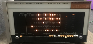
Classic PDP-8 Donation at the RICM

We cleaned lots of dust out of the system. Everything inside looks like it is in good condition.

I took the front panel apart to look at the switch paddles. It is really scary pulling out the really large and thin piece of glass for the front panel. Pivots are broken on 12 paddles, so I have some repair work to do. The momentary contact switch for START feels worn out. The PANEL LOCK switch was loose and rotated several turns which broke one of the wires.

I took a closer look at the processor clock modifications. It looks like they moved the R405 clock from the processor side and to the memory side. Then they wired the the clock signal through a one-shot and to a pulse amplifier that was installed in the original clock slot. I will make a schematic for the modified clock circuit.
 
I am curious as to why they would have modified the clock in this way. Access to the maintenance logs would be really handy. I don't have anything like that for mine either.

I've never seen a mod like that on another straight 8. There were mods on the System Source 8 that I didn't work on (I didn't work on that one because of the mods). I wonder if it was the same? I didn't do a card audit on that machine so I don't know if the R405 was moved there.

The R405 puts out a 100ns pulse. It will be interesting to find out how much they lengthened the pulse with the one shot. And then they gave that a bit more drive. Was this a Band-Aid for some other problem?
 
I took the front panel apart to look at the switch paddles. It is really scary pulling out the really large and thin piece of glass for the front panel.

If this is going to be places in a touchy/feely part of the museum, consider making a plexiglas replica. Then store the original between 2 sheets of corrugated board,, thin hi-density foam, then plywood, carefully dated and labeled if you ever decide to go back to original. OTOH, if it's going in a "behind the velvet rope" exhibit area, better to keep the original glass in it.

I just mention this because your other posts indicate the goal is to return this CPU to fully operational status, which seems to imply a "hands-on" exhibit area.
 
Keeping the original glass should be ok unless the CPU is positioned flush with the front of a cabinet or table. This is not at all necessary because the paddles are enough above the bottom of the chassis that there is plenty of clearance to manipulate them. I have the DEC supplied counter that plugs into the rack just below the front panel. The panel is 18 inches back from the edge and the tips of the paddles are 2.75 inches above the counter when the paddles are down. The counter top is 27 inches above the floor. You can sit in a chair and rest your arms on the counter top while you toggle in the Fortran compiler pass 1 (smiley goes here.)
 
If this is going to be places in a touchy/feely part of the museum, consider making a plexiglas replica. Then store the original between 2 sheets of corrugated board,, thin hi-density foam, then plywood, carefully dated and labeled if you ever decide to go back to original. OTOH, if it's going in a "behind the velvet rope" exhibit area, better to keep the original glass in it.

I just mention this because your other posts indicate the goal is to return this CPU to fully operational status, which seems to imply a "hands-on" exhibit area.

It will be in an accessible area. Nobody has damaged the PDP-8/I, PDP-9, PDP-11/40, or PDP-12 front panels yet so I don't expect any problems with the glass. I may have to repair more switches if we have an exuberant visitor, but that hasn't happened yet either.
 
FYI: I have printed pdp8/L switches using PETG at 220-230c temps and they not only work just fine, but look good and the pivots have held up for 2+ years as the DEP and EXAM switches.

So there is that. PLA will not work at all, PETG is a different animal.
 
FYI: I have printed pdp8/L switches using PETG at 220-230c temps and they not only work just fine, but look good and the pivots have held up for 2+ years as the DEP and EXAM switches.

So there is that. PLA will not work at all, PETG is a different animal.
How did you deal with the switch colours? Did you paint them? I have printed a bunch of them in Nylon and they work really well, but are ugly grey.
 
Companies will colour match the filament for you. Obviously you pay for that service, but if realism is what you want (and not battleship grey)!

Dave
 
My son used to work at a University in the UK where he set-up a number of specialised 3D printing machines (Carbon Fiber and Kevlar) as well as the usual suspects.

They could get hold of Pantone colour matched fiber. Guess where some of my replacement PDP-8 paddles came from!

Dave
 
I took the power supply out of the PDP-8. That was much easier than I expected. Now I can reform the capacitors and see if any of the outputs actually regulate.
 
Would someone like to start a group order for at least the standard colors for the paddles. I would absolutely buy 1KG spools of each color in PETG.
I will even offer to print sets for people (at cost depending on the cost of the filament).

I am running a PRUSA MK4 with MMU3 and Obxidian 0.4mm extruder nozzle.

Last year before VCF Midwest I printed some paddles in PLA (from the stls mentioned here) and they turned out pretty good and that was with the MK3. The MK4 is even better.
 
*nod* I printed mine with the trusty Ender 3d pro. Work and look fine. Granted they are black, but I could easily re-print them in a more appropriate set of colors.

PETG is tough: I printed some bushings for my Porsche 928S seats. Very heavy loads, 4 years in and works fine.
 
I will even offer to print sets for people (at cost depending on the cost of the filament).

I am running a PRUSA MK4 with MMU3 and Obxidian 0.4mm extruder nozzle.

Last year before VCF Midwest I printed some paddles in PLA (from the stls mentioned here) and they turned out pretty good and that was with the MK3. The MK4 is even better.

I would love to have a few spare switch toggles for my PDP-8/e, but I am even more interested in the light/dark green switch toggles used on the LAB-8/e.
 
Once we have found the right colored filament I will be happy to print some for you.
The light & dark green switch toggles are beyond "L@@K RARE". :)
I have never seen any on Ebay ever.
All the switch toggles on my LAB-8/e are intact and in good condition. I have built an acrylic cover to protect the front panel from accidental knocks. Nevertheless I dread the possibility of accidentally damaging a switch toggle in the future while working on the LAB-8/e. So having a few spares would be a good insurance. There are very few complete LAB-8/e systems out there. Other than mine I know of only 2 more.
 
All the switch toggles on my LAB-8/e are intact and in good condition. I have built an acrylic cover to protect the front panel from accidental knocks. Nevertheless I dread the possibility of accidentally damaging a switch toggle in the future while working on the LAB-8/e. So having a few spares would be a good insurance. There are very few complete LAB-8/e systems out there. Other than mine I know of only 2 more.
Repairing a broken pin on a paddle turns out to be easy. I made a drill guide that can be 3D printed. You fit the broken paddle into the guide and then put the top cover on. There is an alignment hole on the top cover which you center on the drill bit. Clamp down the guide to the base of the drill press and then drill out the broken pin. You can replace the pin with any of a variety of rod stock. I favor acrylic rod but I tried piano wire, carbon fiber rod and wood dowel to name a few. The acrylic rod is the least sturdy so it breaks before the switch assemblies which is what you want.

It takes a lot less time to repair than to print a full set of paddles which you would have to do to have all paddles the same color. Even paddles from different machines of the same type don't match anymore if they ever did. Repairing the original broken paddles eliminates the color match issue.

The drill guide is on thingiverse here My drill guide and paddle stl's
 
We think that this system has not been powered for about 50 years, so we removed the H708 power supply from the chassis. The system gets really top-heavy and unstable without the power supply installed. We inspected everything for damage and leakage, reformed the capacitors. and checked the diodes and transistors. We connected it to an AC source through a Variac, and slowly ramped up the AC voltage over about an hour and monitored the 6x output voltages. At about 45% voltage the POWER OK relay chattered and closed. At about 65% voltage all of the output voltages looked reasonable. The Margin Supply actually worked as expected. We reinstalled the power supply and turned the system on. Five if the six fans spun up and some lights on the front panel lit. All of the control switches on the front panel do something. The LOAD ADDRESS switch looks like it is actually loading the switch settings into the PC.

We printed Doug's front panel switch handle drill fixture. This week I will drill out the broken handle pivot pins. I bought some 1/16" acrylic rod on eBay to use for the replacement pivots.

Next week we will determine how many of the bulbs on the front panel are burned out and replace them. We have just a few spare original bulbs. We will also take detailed notes on the switch behavior and start debugging the system.

1717334575023.png
 
Back
Top