• Please review our updated Terms and Rules here

Classic PDP-8 Donation at the RICM

We have just a few spare original bulbs
I bought a bag of original bulbs and some in the bag the leads had already broken off at the base. I've found the CM2187 matches the machines I maintain within the variation of the existing bulbs and has much stronger leads so they don't break trying to remove or install the bulb panel. I've been using them instead of the original bulbs.

Nice progress.
 
I've found the CM2187 matches the machines I maintain within the variation of the existing bulbs and has much stronger leads so they don't break trying to remove or install the bulb panel.

I will buy some from DigiKey and see how they work. We have some original DEC bulbs still in Field Service tool kits.
 
As you will discover, the leads on the original bulbs are so fragile that it makes reassembly difficult without damaging more than you just fixed.

I am going to get some of the suggested replacements and redo all of them the next time I take it apart. I may even go so far as to replace the front panel PCB because the foils are fragile and ham fisted service people damaged them back in the 60's and 70's. I was going to replace everything with LED's but Warren was correct and it just doesn't look right. It could be done with a lot of effort and be pretty good. But it would not be right.

I hope knowing how fragile it all is will help you out. Also, it was not designed with repair in mind. I suggest you keep the bulbs in the Field Service kits as a museum exhibit.
 
I have discovered one thing while I have been soldering on DEC board, be careful with the tempereture on your soldering iron. Higher temperature makes it more likely that the foil separates from the board.
 
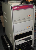
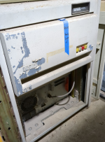
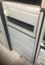
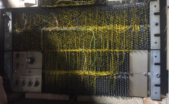
I went shopping for a cabinet in our warehouse that we can put the PDP-8 on and put a DF32 in. We had an early one like the PDP-11 one in the picture. This one is a bit too high and would have put the top of the PDP-8 at about 6 feet high and made it difficult to work on. We had a little 2 foot high one, but the casters were like the ones on office furniture and I was concerned that they might break with the weight of the PDP-8. We3 have an 11/03 cabinet, but I think that it might be too short. I settled on a more modern corporate cabinet because the height is about right. I also found a DF-32 that has the old 24AWG wiring. Hopefully this one has a Negibus interface so it will work with the PDP-8.

I wonder what customer used for a table for the table-top PDP-8 systems?

1717533449617.png1717534139615.png1717533829991.png1717533936614.png
 
Resoldered a broken wire on the PANEL LOCK switch. Testing the front panel switch functions. LOAD ADDRESS works as expected. The SWITCH REGISTER switches need to be cleaned. All of the bulbs in the PROGRAM COUNTER and MEMORY ADDRESS work. EXAM makes the PC and MA count up when the switch is pressed. DEP makes the PC and MA count up when the switch is pressed. and the MEMORY BUFFER contains the switch settings. A subsequent EXAM shows the memory to be all zeros. Bit-3 in the MA is stuck on. Lots of work still to do.
 
It is 1/16" or 0.0625".
I have have lots of 0.0625" diameter Acrylic rod now. I measured the diameter of the very warn pivot pins, and they look closer to 0.050". I will try the 0.0625" Acrylic rod in the metal brackets on the switches before I drill the switches. Hopefully the existing pivot pins are just very warn.

I also got the new bulbs from DigiKey. From my initial testing all of the PROGRAM COUNTER, MEMORY ADDRESS, and MEMORY BUFFER lights are working.
 
I tried the 0.062" Acrylic rod in the metal brackets on the switches. It is a little loose in the holes, but a lot tighter than the original pivots on the handles. This retrofit should work great.

I started debugging why the EXAM and DEP switches don't work. The R405 clock flipchip was moved from slot PB35 to slot the unused slot MF29. The output from pin D is wired to an R602 Pulse Amplifier in slot and then to pin U on the R202 dual flipflop in slot PB34. The CLOCK signal synchronizes turning on the RUN flipflop.

The original wiring that connected the CLOCK output of the R405 to the TG flipflop is not there. I need to reverse engineer this change.

We looked at the signals that are generated by pressing EXAM and DEP. The KEY EX+DEP signal is present on pin N of the R107 in slot PB30. The signal KEY ST+EX+DP signal is also on pin F of the R107 in slot PB33.

We looked at the SP signals that get generated by key presses. The W501 Schmitt Trigger in slot PA36 is gone, and a R302 Delay is there instead. A signal is present on pins H & J of the S111 in slot PB31. The signal goes active if START, LOAD ADDRESS, EXAM, DEP, or CONT is pressed. We looked at the SP0 signal on pin E of the R302 in PA35. We see a signal when START or LOAD ADDRESS is pressed, but not when EXAM or DEP is pressed, and only once when CONT is pressed.

I am not sure how EXAM and DEP will work with the modifications that were made. Maybe we should put everything back to the factory wiring?
 
It is 1/16" or 0.0625".

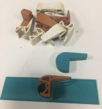
I tried drilling the broken handles with a 1/16" drill and the 1/16" Acrylic pivot rod would not fit in the drilled hole. I tried a #52 (0.0635) drill and that fit much better. The diameter of the Acrylic rod is not too consistent along it's length, but it should work just fine.

Thanks for sharing the design of the drill fixture. It worked great!
Glad to hear it!

I think I used a #51 and then a drop of superglue to hold the acrylic rod in place.

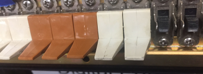
The fit of the 1/16" acrylic is better than the original pins. If you wiggle the paddles the repaired ones are much less sloppy.
 
Do you have any pictures to share?

This is really fiddly work. Some of the pivot holes were drilled about 0.030" closer to the switch than original pivots. After installing and trying the fit, I found that I had to carve a little plastic off the switch to make room for the metal bracket on the switch. As Doug said, there is a lot less play in the repaired switches compared to the originals.

1719432415871.png1719438720518.png
 
Last edited:
This is really fiddly work. Some of the pivot holes were drilled about 0.030" closer to the switch than original pivots. After installing and trying the fit, I found that I had to carve a little plastic off the switch to make room for the metal bracket on the switch. As Doug said, there is a lot less play in the repaired switches compared to the originals.

View attachment 1282102View attachment 1282103

What is your technique to get the switch handles in and out without damage to either switch or handle pins?
 
What is your technique to get the switch handles in and out without damage to either switch or handle pins?
I've had some luck (with 8/E and 8/L switch handles) engaging the pin on the "open" side, then sliding the handle in that direction until I can get just get the other side engaged. This assumes the gap is more than one handle wide. For the one handle case, it's a fiddly thing involving fine blade screwdrivers to flex the metal tabs. I also have one machine where all the "spring" has left the metal tabs, so that you have to flex them back closed around the switch handle. That is a total pain, as the clearances just aren't much.

Fortunately, once you get the thing together and racked, I find that it's most often the deposit switch handle which gets damaged, and it is slightly separate from the others.
 
What is your technique to get the switch handles in and out without damage to either switch or handle pins?
I have been doing the same as Vince. Getting the switches out was easy because the pivots were broken. To put them back in, I left the left metal tab in the normal position and bent the right tab away from the switch. That let me engage the left pivot in the tab, push it to the left a little, put a tiny screwdriver between the switch handle and the right tab, gently pry the right tab so that the right pivot will slide into the tab, and finally bend the tabs so that they are parallel and minimize the side-to-side play in the handle. I have the luxury of having all of the switches removed to the right of the one that I am reinserting, so I have more room than normal to work.
 
I have been doing the same as Vince. Getting the switches out was easy because the pivots were broken. To put them back in, I left the left metal tab in the normal position and bent the right tab away from the switch. That let me engage the left pivot in the tab, push it to the left a little, put a tiny screwdriver between the switch handle and the right tab, gently pry the right tab so that the right pivot will slide into the tab, and finally bend the tabs so that they are parallel and minimize the side-to-side play in the handle. I have the luxury of having all of the switches removed to the right of the one that I am reinserting, so I have more room than normal to work.

This process didn't work today. I spent 2.5 hours fiddling with the pivot on one switch and never got it to fit right. I found that the diameter of the 0.0625" Acrylic rod varied from 0.060" to 0.070" along the length of the 18" long rods. I will have to cut out the parts that are 0.062" or less and use those parts.
 
Back
Top