• Please review our updated Terms and Rules here

Columbia Data Systems 1600-VP CRT issues

If you look at the schematic for the Elston DM30 monitor (seems to be a kissing cousin to the one shown, particularly for its use of NE555s in the horizontal circuit), the video input is analog. In any case the 7486 mixing circuit should work fine, as the video is "straight through", with the '86 simply combining the sync signals to ride on the video output.

 
Again, my point is just it might not even be necessary to build the sync mixer if there's an intermediate board in this system that's already taking composite from the system board and splitting it for the monitor. Just cut out the middle man.
 
Is this the video card in the machine? If so, there's definitely composite video available via the RCA jack. The CDP video card was a more-or-less copy of the IBM CGA. It's hard to believe that the VP is that much different from the MPC.
 
It looks like the VP had its CGA clone video integrated onto the motherboard. Unfortunately the only picture of the motherboard I can find is too small to make out the video connector.

The IBM 5155's display also connected to its CGA card with a three pin connector; the three pins were ground, composite video, and +12v driving the whole show. It's certainly possible the VP uses a similar setup.

Edit: This thread has the only pictures of the inside of this beast I can find.]...
 
Last edited:
I do wonder if there's something I could do to get video out of the 3 wires that come from the motherboard to the CRT connector. I have to assume it's video, H sync, and V sync. Is there any way I could utilize these signals to get some form of display working? Something like composite, component, or similar?

Could you clarify how the wires coming from the system board are connected? IE, if there are wires coming straight from the motherboard to the 10 pin connector on the monitor and not going via an intermediate board (looking at the few available pictures I found the only other board in there is the one with the power supply components on it?) which three pins on the monitor do they connect to?

If there are *three* wires and they go to video and two syncs then the system must rely on power supply common grounds for the signal ground... which I guess is fine. *If* that's the case then, yes, you'll need a sync combiner like Chuck's linked to. Here's a dumber version using only a single transistor instead of the XOR gates, which *may* work depending on how tolerant your monitor is. The question that would remain is how high level the video output it; it's clearly analog, since it's capable of shades of gray, but it may well not be the standard 1v peak-to-peak signal level of according-to-Hoyle "analog video" as used for VGA or for standard composite video levels. You might need to muck around with some different resistors to get proper signal levels out of this monster.

(On the bright side signal levels aren't usually that *critical*, as long as the output isn't so "hot" that it damages your monitor you'll probably at least get something you can read well enough to tell you if the thing is broken or not.)
 
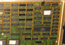
Glancing back at my old photos I took, here is a higher resolution image of the video section.
 

Attachments

  • m.jpg
    m.jpg
    231.3 KB · Views: 5
Glancing back at my old photos I took, here is a higher resolution image of the video section.

The video connector is the three wire plug in the upper right next to R3/R4?

If the color codes of the wires match up with the OP's diagram on the previous page then, assuming everything was counted from the correct ends, those are indeed Horizontal Drive/sync, Vertical Sync, and Video. (Brown, orange, and white respectively.)

The thing that gives me a little pause is the "Horizontal Drive" might not be an according-to-Hoyle "sync" quite like that on a CGA monitor; it might be more like the hdrive on a Commodore PET? (The adapters for that use various methods to turn a full sweep drive signal into a pulse.) Sticking a scope on these would probably be useful.
 
I suspect the "drive" is more like the horizonal signal on the MDA--it doesn't sync an oscillator, but is merely amplified by the monitor.

But you'd think that part of the bundle of 3 wires would include a ground return for the signals...
 
But you'd think that part of the bundle of 3 wires would include a ground return for the signals...

I know, I'm kind of hung up on that myself... but *technically* they could be using a common ground through the power supply harness. It's kind of gross but should work?
 
I took a quick look at mine and verified none of those are ground. I guess the idea is it only goes to the CRT connector, and that already has a ground.

Tried connecting each one individually to the composite in of an Apple IIc CRT. One showed a wiggly white bar down the center of the screen (h sync), the other seemed to show a white bar across the screen just off of the bottom (v sync), and the other showed out of sync text (video, out of sync because I don't have the above circuit to combine the signals).
 
SomeGuy, did the signals match the diagram I made earlier?
 
While looking up the chips near the 6 pin, unused header near the video circuit, I noted that one is a Motorola MC6845P "CRT Controller". Does that change anything about the video signal we expect to see from the 3 wires? And speaking of the 3 wires, the header for those is actually a 4 pin header. I verified with my multimeter that the 4th, unused pin is ground. But it would be chassis ground, which I think may be different from the power board's generated ground. Although many of the chips on this board, the MC6845P included, use this ground, so I suppose it's the ground we would care about.
 
It's the ground you want to use. Since most designs bond the chassis to signal ground, there's not difference.

The 6845 is used in a wide range of PCs (and other computers). The PC platform uses it for CGA and MDA. Standard fare.
 
Just out of curiosity, I took mind apart to look at some of this stuff.

First of all, I tried setting the DIP switch to have it redirect I/O to the serial, and off hand I could not get that to work. It would just beep, sit there for a while, and eventually boot, with nothing going to the serial port. Tried various settings, starting with that is specified in the 1600 MPC manual. Serial port works fine, can CTTY or pipe output typing commands at the keyboard.

That 6-pin header seems to have nothing video output related. Still not sure what it is for.

Looking at the components near the video output, there are four resistors. I think those are combining the R, G, B, and I signals for the video output. So sampling before the resistors might get a proper RGB. But I don't have time to test that.
 
Ah, ok. I didn't know if it being a "CRT Controller" changed what type of signal it might be generating. Good to know.

Back to the CRT driver board. I ordered the all of the electrolytic caps except for the big non-polar cap. In the mean time, I've been poking around the board with my multimeter. If you recall, something is pulling the +12vdc down to +8vdc when the board is connected, so I assume something is shorted. I only know how to do some rudimentary checks and even those, I'm not entirely sure of. I figured I'd find anything that looked like a short, report back here, and see what the experts say.

I found two possibilities. Both capacitors, neither electrolytic (I think). The first is a small cap next to what I believe is a transistor and a transformer. There are two capacitors of this type and value on the board. One reads open, which is what I expected, and the other reads shorted at 0.2 ohms.
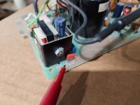
suspect_cap1.jpg

The other possible problem cap also has others around it of the same type and value. They all test "open". The suspect cap reads 99.9 ohms. It wasn't enough to make it beep, but I still thought it was worth asking about. I don't know if either of these are expected due to other nearby components. I know that testing components in-circuit can be iffy, but I'm not going to remove each component to test it. I suppose I could remove those two and see if the values persist.
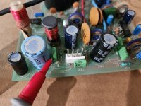
suspect_cap2.jpg


I think I'm going to start a new thread to post general information about the VP into, since this one is really a diagnostics thread that has gotten a little out of scope. I took some high resolution photos and think I have a better idea of what some of the various headers are for (not the 6 pin, sadly) as well as I've found some pictures of a different version of the board that has some differences from mine.
 
Looking at the components near the video output, there are four resistors. I think those are combining the R, G, B, and I signals for the video output. So sampling before the resistors might get a proper RGB. But I don't have time to test that.

The composite output on CGA consists of a resistor ladder on RGBI to get the grayscale (luminance) value and a separate circuit that creates pulses based on fractional phases offsets from the NTSC colorburst which are mixed in via another resistor to create the chroma signal for a color monitor. I would bet that the "CGA" circuitry in the VP omits the composite color generation goo but generates the grayscale analog video output for its internal monitor similarly so, yeah, you probably could effectively recreate a digital CGA signal by sampling behind the resistor ladder.
Ah, ok. I didn't know if it being a "CRT Controller" changed what type of signal it might be generating. Good to know.

A thing to know about the 6845 is it's not an all-in-one video generator; it generates sync framing and spits out character row and framebuffer memory addresses but the actual pixel generation and a number of other details are left to supporting circuitry. Because of this there's no guarantee that if you have, say, two machines that both use the 6845 to drive "NTSC-ish frequency" monitors but one actually has a composite port while the other drives a digital monitor that they program their sync signal generation identically....

That said, though, I think it's probably a fair bet they pretty slavishly copied the CGA BIOS and the thing is producing CGA-ish looking sync timing, so if you still want to try hanging a composite monitor off the the signals that are there... that circuit with the 7486 on the previous page is might technically be a little more complicated than what you actually need? If you have an oscilloscope this page has some scope pictures of the hsync and vsync signals from a CGA card. Comparing the scope readings from the lines on the VP that we *think* might be the hdrive and vsync signals would tell us what adjustments need to be made to make a working sync converter(*). If they're basically just CGA sync then the schematic in that article is a little simpler than the last one; you could also take it down to one chip instead of two by using one of the unused XOR gates in place of the separate inverter. (The "CGA/MDA" switch on the previous page's schematic is an invert/don't invert switch for the final output, just copy that.) Feed the combined sync into an adjustable trimmer resistor and tie that with the "video" line. To really make it kosher you'd probably want to run it through an ouput transistor and terminate it to ground with a 75 ohm resistor, but I know from some of the fooling around I've done with homebrew video you can probably get away with a more ad-hoc setup if the goal is just to test it.

Edit: Here's a link to the manual for a monochrome CRT chassis with a similar 10-pin connector. This says it takes a negative-going vsync... but positive is an option, and a "5u-40uSec Positive Going Drive" for horizontal. So yeah, getting a look at what's on the wire would be useful to figure out if the pulse length needs to be reshaped.
 
Last edited:
Let me ask a couple of bonehead questions with regard to the monitor.

1. In a darkened room, with the computer turned on and booted, can you turn up the brightness control so that you can see a raster on the screen?
2. In the same darkened room, can you see the heater at the rear of the CRT glowing?

One suspect pulling things low might be the horizontal output transistor. Certainly worth checking before going after all the capacitors.
 
Back
Top