A MIHV-to-composite video is pretty easy to construct. I used this circuit over 40 years ago to adapt our system's video output to a 24" monochrome studio monitor for classroom use:
See Option 2
I took a look at option 2. I'm no electrical engineer (I'm a code monkey!). I can read part of the schematic, but not all of it. My first question is what's the IC labeled 7486? I googled "7486 IC" and "7486 chip" and didn't find anything that sounded correct. I assume it's an IC anyway! Also, I have some questions about other components. Some I think I understand, some I definitely don't:

1) What is this component and I see that it connects to the HSYNC, but does the other side of it connect to something else, or is this something that sits in-line?
2) Is this an adjustable 2k2 pot? Is the 2k2 value it's upper, or "highest" resistance value?
3) I don't think I have an intensity output available, although the connector for the video signal where it plugs into the motherboard has an extra, unused pin. Perhaps this is intensity? I don't know how I would verify that.
4) I believe this is a switch to switch between MDA and CGA video input, is that correct? It looks like there would be two of these switches, one at the input (between pins 6 and 7) and one at the IC connecting pings 13 and 14 for CGA and connecting pin 14 to Ground for MDA?
5) That's just a connection to +5VDC, correct? Won't the switch to MDA that goes to ground cause a short? Or will this just "pull the pin down"?
6) I know that this is a diode, but does "2x 1N4148" mean "two 1N4148 diodes" and if so, are these in series or is the second diode the one shown below it going the other direction?
Sorry for all the questions. Just trying to wrap my head around it all.
I bought a GBS8200 hoping it would be able to translate the signal to VGA since it purports to do CGA and EGA. This was unsuccessful. Is that because my signal is actually MDA? I've also read that these GBS8200's need an analog signal and that computers usually output digital. Is that part of my problem?
First of all, I would take the floppy drives out and verify their functionality on another computer. They may need a good cleaning.
The desktop Columbia Data Product 1600 MPC has a feature in the BIOS that enables text BIOS I/O to output to its serial port. Flipping the first DIP switch on the motherboard enables that. I've booted generic DOS 6.22 on a 1600 MPC before and was able to use most command line tools with it via a terminal program running on another computer.
The BIOS on the VP is the same, but I have never tried that on the VP. The case has to be disassembled to get at the motherboard DIP switches.
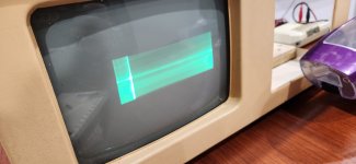
The video signal to the CRT board should have the same sync timing as composite video. I'm a little surprised they did not include a composite output port for an external monitor on the machine. The Compaq Portable did.
I had noticed some early Kaypro computers used a similar CRT board. I had also wondered if they would work.
I have plans to tear them down and clean/lube everything. That part I've done with great success on a few machines that had inoperable drives. But I'm focusing on getting some usable video signal of some sort first.
This might be an option, although I'd really like to get the onboard video displaying either to the CRT or to an external monitor of some sort. But it's good to know that it has that capability. At least that way I can see if it's booting and functional.
I had hoped I could just hook the video/sync signals up to the GBS8200 board or directly to a VGA monitor, but neither worked. The GBS8200 flashed a green solid screen a couple times, then went black and stayed there. Hooking the wires directly up to VGA's Green, HSYNC, VSYNC, and GND pins just got a "Signal out of range" message on both LCD screens I have that have VGA in. My understanding is that to get composite out, I would need to combine the HSYNC and VSYNC together using either logic gates or an IC designed for the task. It also sounds like the signal from the board may not be in the right frequency range for my modern hardware to pick up. Is this correct?
I'm kind of surprised someone hasn't come up with a pre-made board for these types of things. Then again, I guess in most cases, you'd just stuff a video card in it and call it a day. I do have a pair of ISA video cards on the way from eBay. One is an 8 bit VGA card that I bought before reading your thread where you mention the newer BIOS being required for VGA, and an 8 bit CGA card with both db-9 and composite output. I'm hoping between the two of them, I can get some sort of output!