• Please review our updated Terms and Rules here

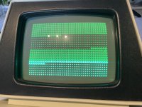
Commodore 3016 scrambled screen

Till now i checked traces from pin to pin. Checked some IC's with retro chiptester.
I am also building a tester for the PET(PET-Diagnostic-Clip) . Waiting for some parts.
Interesting, I had not seen that PET diagnostic clip before. One feature of it I like (or at least the original version) is that it clips onto the CPU with a logic clip, so there are no wear issues on the CPU socket.

The CPU and other sockets, especially the original PET ones which were single wipe, are very unforgiving if a larger than normal sized pin is fitted. They lose spring tension easily and later then are a loose fit for the IC. Though there is one advantage, in that their design allows the plastic shroud to be lifted off from the top, much like the horrible TI sockets that grip the pins side to side. This means the pins can then be removed one by one prior to solder sucking the holes and this puts minimal forces on the holes, pads & tracks.

Machine pin sockets are easily damaged too. For my vintage computers I always re-fit dual wipe sockets, as they are more forgiving and I lubricate them too with mx-3. One advantage of the dual wipe with the thin flat pins, they are much easier to solder suck and remove than a machined pin type. Also their pins (claws ) can be extracted from the top one by one if required. After solder sucking the pin is easily released in the hole with sideways movement to free them all before the socket is lifted free.

The machine pin type, that cannot be done easily and the pin occupies a greater cross sectional area of the hole and even with good solder sucking they can stick to the sides of the plated through hole and there are more risks to the pcb removing the socket than with the dual wipe type.
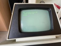
I am building this one:
https://github.com/svenpetersen1965/PET-Diagnostic-Clip
It's based on the 'original' one

And i also replacing one by one the sockets by new ones. I am then using the round pin ones.
Also checking some other Logic IC's by unsolder them and test with the RetroChipTester and then first solder also a socket for that ic.
 
That looks good.

Ah, the old UD8 and UD9 problem. Only the most important ROM sockets!

IEEE488 port to test now...

Dave
 
I forgot to mention.. When turning on there is few seconds some scrambled screen. After that a blackscreen.
If i use the PETTESTER, you see only one letter in the screen. If i use my other Pettester the first screen is correct. So there is some screen.
 
I have seen this screen before - on the machine of @Desperado.

I am not sure what you are saying regarding the multiple PETTESTERs...

Your display indicates that the first 256 bytes of memory are GOOD and the second 256 bytes of memory are BAD. However, the BAD bytes all return the character code for a '.' - which is unlikely. There was a bug in my PETTESTER a long while ago that did this - but the V04 on my Google Drive has it fixed. Where did you get your copy of my PETTESTER from?

Dave
 
Last edited:
OK, so you have exactly the same fault as @Desperado...

I am going to have to think about that one now (again) aren't I...

Dave
It is interesting, maybe if you find the cause of this, you will be able to fix two computers in one go.

@TheMatrix: it is a good idea to turn the CRT brightness down as far as you can (your image shows the raster and retrace lines). Actually, in these PET VDU's with the Green CRT it is an interesting story. The 9" VDU was basically a copy of part of a portable Zenith TV set that used a 9VALP4 (white crt). Its gun only required around -30v g1 voltage to cut off the beam, but the green CRT it is more like -40 to 45v.

Therefore, in the VDU's with the green screen like yours, even with the brightness control set to min, the sub circuit does not supply enough negative voltage, often the beam is too bright. There is a simple mod in the article I wrote of how to fix this and get more range out of the control, by adding a few turns around the transformer core.

It pays to run a CRT with just the required brightness level to see easily, there is less chance of getting the phosphor burn in effect (de-sensitization of the phosphor) plus the beam focus is better too and you get sharper text and graphics. Same basic principle with scope tubes. I hate it in the movies, where you often see a scope running in a lab, with a low time-base speed and the brightness turned way up. I have been guilty of walking into workshops and turning the scope beam brightness controls down. Its like walking into a room where the hue, saturation, brightness and contrast are way off on a color TV, and adjusting the TV, that can annoy some people who think the picture was better the way they had it where everything looked like an overexposed cartoon.
 
It is more likely in the RAM or RAM CONTROL section not the EPROMs.

Can I ask when you downloaded my PETTESTER? The fix was in V4.3 on 2nd October 2019 - so very old. If you obtained it from my Google Drive - you should have the source code - and this should be the last entry in the modification header.

Dave
 
I have an inkling what is going on. I haven't worked out why though (yet). I am working on that!

I write the values of $00 to $FF into both pages 0 and 1 at the same time.

I then test that page 0 has the correct values - and update the screen display accordingly.

I then test that page 1 has the correct values - and update the screen display accordingly.

The screen contains one page for the VDU 'g' or 'b' character followed by one page of '.' characters (assuming a 'g' - GOOD - status).

If writing the '.' characters to the screen at $8100 to $81FF happens to also write to the DRAM at $0100 to $01FF that would store a '.' into the screen to indicate that DRAM page 0 was OK - but we now accidentally overwrite DRAM page 1 with a '.' character (!) and it subsequently tests as bad.

Now, to work out what the most likely candidate is. I am leaning at A4 or A5 at the moment - but give me a little time...

EDIT: I am thinking H5 or B2. It would be interesting to check H5 pins 1, 2 and 3 and B2 pins 8 through 13.

B2 decodes when the RAM should be selected. if B2 is duff - then the DRAM could be selected when it is not supposed to be.

H5 triggers the DRAM state machine to initiate a /RAS and /CAS cycle. This could also trigger a premature DRAM write when it shouldn't.

The video RAM (that we should be writing to) and the DRAM (that we should not be writing to) share the same data bus buffers - so the data bus (and, therefore, the associated data bus buffers) are in WRITE mode by default - so the same data (a '.' character) will be presented to both the video RAM (that should store the value) and the DRAM (that should not store the value).

This is a 'doozy' of a fault (if it turns out to be 'real')...

I am also guessing that page 0 RAM will get overwritten by a 'g' - but the test has already been performed and proven to be good!

EDIT: @Desperado - please read this post, it also applies to your machine...

Dave
 
Last edited:
OK, what about H4? That is next in the line...

Also, can you check to see if there is a video RAM write on F6 pin 7 coincident with a DRAM /CAS0 on G7 pin 12 please?

Dave
 
Back
Top