- VCF South West - June 14 - 16, Davidson-Gundy Alumni Center at University of Texas at Dallas
- VCF West - Aug 2 - 3, Computer History Museum, Mountain View, CA
- VCF Midwest - Sept 7 - 8 2024, Schaumburg, IL
- VCF SoCal - Mid February 2025, Location TBD, Southern CA
- VCF East - April 2025, Infoage Museum, Wall NJ
-
Please review our updated Terms and Rules here
You are using an out of date browser. It may not display this or other websites correctly.
You should upgrade or use an alternative browser.
You should upgrade or use an alternative browser.
Commodore monitor 1084S-P and PHILIPS CM8833II
- Thread starter demonlg
- Start date
daver2
10k Member
It certainly does sound that something (line output stage) is under stress - either something is shorted or...
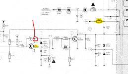
I am just contemplating how to move forwards with diagnosing this issue. I am just debating removing resistor 3520 (10 Ohms) to disable the line output drive supply voltage and to check for a healthy line drive signal at the collector of transistor 7510 (BC639).
Just thinking...
Dave
I am just contemplating how to move forwards with diagnosing this issue. I am just debating removing resistor 3520 (10 Ohms) to disable the line output drive supply voltage and to check for a healthy line drive signal at the collector of transistor 7510 (BC639).
Just thinking...
Dave
daver2
10k Member
Yes and yes...
With the resistor removed the monitor should also stop screaming at you...
Dave
With the resistor removed the monitor should also stop screaming at you...
Dave
Last edited:
If i remove the 10ohm5W ceramic resistors (good) the whistle is not present, and i have same signal of 1084 with scope, i don't make a photo now but is the same with C64 connected on the input.
This resistor put the +128c in the flyback input, first indicate is it to fault, or the H transistor, but it seems good.
This resistor put the +128c in the flyback input, first indicate is it to fault, or the H transistor, but it seems good.
Last edited:
daver2
10k Member
I am in meetings all afternoon.
I suspect (like you do) that the output drive transistor is fine - otherwise it wouldn't be screaming...
I would check diode 6546 (1n4148) for short circuits, as I would capacitor 2547 (2u2). Unlikely culprits though...
Can you disconnect the scan coils (connector M4) to rule that out.
EDIT: You will have a low resistance between pins 3 and 5 I am afraid - it is an inductor...
EDIT: Do you have the reference oscilloscope traces to go with the numbered circles on the schematics?
Dave
Hugo Holden
Veteran Member
I wouldn't get too excited about the audible whistle. In general, given that the H output stage runs above 15kHz, this is not audible to most people over 50 years old. So if you hear a whistle, like the one in the video, it is a much lower frequency, probably well below 10kHz, suggesting something is off with the drive frequency. Any of the inductors can make this noise and on occasions, capacitors do to too.
The thing to do, as Daver2 suggests, is to disable the H output stage by disconnecting the HV supply to the flyback transformer. Then the drive frequency can be checked on the scope
The thing to do, as Daver2 suggests, is to disable the H output stage by disconnecting the HV supply to the flyback transformer. Then the drive frequency can be checked on the scope
daver2
10k Member
Hugo,
I think he has just done that in post #27 (if I read between the lines)...
Dave
I think he has just done that in post #27 (if I read between the lines)...
Dave
I have checked the board, because this is used for parts, and i have missed to resolder the C2520! It Is in previouse schematics between pin 3 of flyback and GND (10uF 160v)..i have to found it, and test again, but I don't think the lack of this can cause the whistling I mentioned before since by removing the +128 to the flyback the whistling stops.
Emanuel
Emanuel
Ok, I found the necessary capacitor missing, but as I imagined, the whistling didn't depend on that, the only change is that when I turn it off it lasts longer before it stops, a few more seconds.
Now since the components are really all there, since I tried the horizontal transistor by unsoldering it and it turns out good, and since without the +128v that feed the flyback primary the whistle stops, what about the EAT change?
I have tested also diodes 6546 6440 and 6441 and capacitor 2547 and all are not in short.
Tested also without yoke connected and the issue is the same.
Last edited:
Ok, hugo, totally understandable, I start by saying that I'm 46 years old :D, and I can often hear the hiss of the EAT as I get closer, but this doesn't come from the EAT but from the PSU. The larger capacitors have all been replaced, including the missing one that I mentioned before, only the small electrolytics and the NP remained.I wouldn't get too excited about the audible whistle. In general, given that the H output stage runs above 15kHz, this is not audible to most people over 50 years old. So if you hear a whistle, like the one in the video, it is a much lower frequency, probably well below 10kHz, suggesting something is off with the drive frequency. Any of the inductors can make this noise and on occasions, capacitors do to too.
At this point I'd say that I'm forced to solder the wires on the PSU outputs again and check that they're all there, keeping the 10ohm5W resistor that powers the EAT disconnected, and think so if one of the voltage is faulty or not regular i have to check in the corrispondent area of working.
daver2
10k Member
Yes, check that the PSU outputs are still OK (with the resistor removed).
I would then be tempted to reinstall the resistor and VERY QUICKLY check for the presence of the -27V supply on C2541 and 23.4V on C2547. You need to be pretty quick with these measurements (if you are going to do them) because the problem area will be stressed. Get the meter connected etc. before hand so that you are ready to take the measurement and switch the monitor off quickly.
The other possibility would be to remove components attached to the output windings of the fly-back transformer and see at what point the screaming goes way.
Hugo, thoughts.
Dave
Ok, I try as you said, however normally I do this to measure the voltages when there is something like this, I connect the multimeter leads before powering up and then power up for 1-2 seconds maximum to read the voltages.
However, I tried again without resistance just to hear if I heard other strange noises, I only hear the PSU whistling at startup like all the other working monitors and then it stops, or rather I don't hear it anymore.
Now I measure the voltages by soldering the wires as done on the 1084S-P1 and report them here.
Emanuel
daver2
10k Member
Sounds like a plan.
Dave
Dave
daver2
10k Member
No potential problem there.
The 9V rail is a bit low - but this is an unregulated supply.
The 5V rail is also a bit low - bit this is a very simple regulator (and not a high-accuracy IC regulator).
Looks OK.
Dave
The 9V rail is a bit low - but this is an unregulated supply.
The 5V rail is also a bit low - bit this is a very simple regulator (and not a high-accuracy IC regulator).
Looks OK.
Dave