• Please review our updated Terms and Rules here

Commodore monitor 1084S-P and PHILIPS CM8833II

Now, the check for the presence of the -27V supply on C2541 and 23.4V on C2547 with 10ohm resistor reinstalled:

-27V not present on C2541 but i have tested it at the point in photo marked -27v (the C2541 is in a unconfortable position for now)

23,4 volt con C2547 is 22,2v when powering on for one second the monitor, then slow down to 0v when powering off

In the photo the 3510 solder point are the ceramic resistor 10ohm.
 

Attachments

  • -27v point.jpg
    -27v point.jpg
    309.9 KB · Views: 4
Again, those voltage readings are not too bad.

Let me think a bit more... Tea time in the UK!

Just a quick thought. What happens if you disconnect the connector from the rear of the tube? Leave the EHT cable connected though. Does the scream go away or not? Again, a very quick check...

Dave
 
Aaaa, you are in UK, I thought you were in the USA! Good tea time Dave.

If i remove he neckboard from the tube i have the same scream!
 
Not this Dave... There are a few "PET Dave's" all over the world!

Homemade Pizza for tea!

So it is either the electronic circuitry or the EHT/FOCUS connection to the tube...

Dave
 
Ehm.......i have missed another two caps!!!! Sorry sorry sorry for my distraction.........this two in attached area of schematics, the first 8n2 is now replaced, but i dont' find one 1uF 250v for the other....

I'm going to find one in other boards i have for spare, but for now i have oncly 4,7uF 250v
 

Attachments

  • another missed caps.png
    another missed caps.png
    70.9 KB · Views: 7
Dave can i try with 4,7uF 250v if scream or it's a problem or cause another problem?
 
Give it a try (providing the voltage is at least as high as the recommended component).

It is also polarised, so make sure you install it the correct way around.

Even if it doesn't 'fix' the problem - it may 'change it' to give us confidence that this is the cause.

Dave
 
I have installed the 4,7uF 250v (original 1uF 250v) and now the monitor don't scream!

mmmmm
 
Ok, now the screen it's starded with raster lines, probably have to regulate the G2, same of the 1084S-P1, but in this case is highest and not lowest!

But the flyback it's good at this point!

Emanuel
 
Excellent. So having all of the (important) components installed is a help :).

I would suggest getting the correct capacitor installed before going too far. It may be part of a tuned circuit.

Dave
 
Yes I agree, I just kept it on for a few more seconds and tried setting the g2 on the flyback to minimum, but the screen lights up a lot and the retrace lines remain.
Honestly now that I remember the defect from a while ago before I used it for spare parts it was just that.

I will try to find a correct capacitor and then try again, but it seems strange to me that with the G2 at minimum the tube still lights up so much.
 
Last edited:
The main thing that controls the overall brightness is the relative G1 grid to cathode voltage of the CRT. The cathodes are set by the video output stages. The G2 "grid" which is the first anode, will also affect it too. So it is a matter if testing those three voltages. If the cathode voltages are not very similar, it will cause a large color imbalance in the raster as one or more guns will be biased differently to the others. Probably, if the color balance is roughly right, the cathodes voltages will be correct (unless the fault is affecting the three video output stages identically), so it is just a matter of testing G1 and G2.

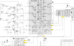
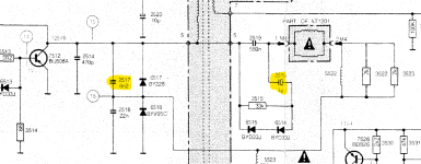
It could have been possible the one of the inductors 5524 or 5523 could have been making noise. As I recall there was a fault in one of these sets recently where the pot 3534 had stopped working and inductor 5524 was open circuit, so the East-West modulation had stopped. Though an O/C inductor would not be noisy.

(One tip about the flyback transformer's main primary tuning capacitors (these are on the collector of the H output transistor and transformer primary to ground) sometimes two are used in series, 8n2 & 22n in this case in this case.There is also a 470pF but that value is not as significant. Never disconnect them or alter their uF value. They determine the peak voltage of the flyback pulse and the EHT. If they go open circuit or are disconnected the peak flyback voltage goes very high, risking the H output transistor, the flyback transformer and the EHT diode inside it. Failure of these capacitor/s is a major disaster. They are also selected to be very high voltage type, typically with welded lead to plate construction)
 
Last edited:
Ok, i have to check g1 and g2.
was just looking at the schematic to see where to measure the voltages on the neckboard of the tube, do you think that could be the problem?

I kind of got the impression that if it stays on too long something is going to shut down the deflection stage, could it be the x-ray protection circuit?

Emanuel
Since the auxiliary voltages generated by the flyback transformer , are all from that source, even if one is correct, likely the others cannot be higher than normal. If the EHT was too high, enough to be generating X rays, the raster scan would have a different size. The scan you end up with in magnetic deflection is inversely proportional to the value of the square root of the EHT. If the EHT doubled, all else equal (extreme example) the whole raster would shrink in size to about 70% normal size and be much brighter. So if you are working on a VDU and the raster scan size is about right then you can be fairly certain the EHT is about right and you don't have to bother to measure it. But, say if the raster scan was enlarged, the beam focus off, you might wonder if the EHT was running low.
 
G1 appears to be pin 5. The schematic indicates 28V, but I suspect this to be negative.

G2 appears to be pin 7. The schematic indicates 370V.

These should all be DC voltages relative to 0V/GND.

Just take care when measuring G2. If you are attaching homemade wires/probes make sure they are rated for at least this voltage.

Dave
 
The part of circuit involved is this? Because i don't find all voltage signed on schematics, yes i have readed -27 on one side and 28 to the tube!
 

Attachments

  • neck and flyback output.png
    neck and flyback output.png
    417.7 KB · Views: 3
G1 appears to be pin 5. The schematic indicates 28V, but I suspect this to be negative.

G2 appears to be pin 7. The schematic indicates 370V.

These should all be DC voltages relative to 0V/GND.

Just take care when measuring G2. If you are attaching homemade wires/probes make sure they are rated for at least this voltage.

Dave
The cathodes sit at 110V( probably a black level value), so with +28V on the grid the grid is still 82V negative with respect to the cathode, more than enough to cut off the beam, I would have thought, just have to check the whole schematic...yes, definitely fed by a -27V source, giving a total effective grid bias of around -138V to cut of the beam, that CRT must require it.
 
Last edited:
G1 should definitely be negative. It is fed from a negative DC voltage derived from the flyback transformer. The AC is rectified by a single diode and smoothed by a capacitor. The polarisation of these components are consistent with a negative rail generation.

Some errors in documentation are accidental, others are deliberate!

Dave
 
Back
Top