• Please review our updated Terms and Rules here

Commodore monitor 1084S-P and PHILIPS CM8833II

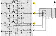
Actually, if that -27V supply failed and went to 0v (say if the diode or the 1.5R fusible resistor 3540, went open circuit) that loss of grid bias might be enough to brighten up the raster to the extent that is being seen. In that case, if that fusible resistor is open, it would also be worth checking the capacitor 2541 ,22uF, for leakage.
 
The -27V rail should have been tested back in post #41.

But it won't hurt to measure it again - especially if it is tested at resistor 3138.

Dave
 
The -27V rail should have been tested back in post #41.

But it won't hurt to measure it again - especially if it is tested at resistor 3138.

Dave
Yes, good idea.

(maybe there was some confusion about which 27 or 28V supply was being checked, this one, sourced from the flyback transformer, or the +28 from the psu, which is oddly labeled as "28V2" and -28 at the psu)
 
Resistor 3540 is ok, 1,5ohm, caps and diode i have to remove again all board for desolder... i try.

Can i solder wires on the tube socket soldering point to measure G1 and G2?

Emanuel
 
Resistor 3540 is ok, 1,5ohm, caps and diode i have to remove again all board for desolder... i try.

Can i solder wires on the tube socket soldering point to measure G1 and G2?

Emanuel
yes, you can measure the voltage at the tube socket. You can solder to the pcb there if you like, normally one would have the negative of the meter connected to common with a clip, and just touch the meter probe on the test point, but if you feel more comfortable soldering a wire and connecting the meter up before you turn the set on, that is ok too.
 
Ok, i have measured both, G2 is 148v and G1 is -27v, seems to be low G2, at the moment the G2 regulator on flyback is at minimum range.
 
Yes, G2 is way low - assuming we have our reference voltage correct as GND.

It should tell us in the manual where the voltage reference is taken from (but I am guessing GND).

Dave
 
I have measured with negative leads connected with clip on a one black wire in the main video board.
 
It doesn't really stack up, in that if G2 was that low, the raster would be dimmer. The G2 voltage is sourced from the focus resistor bleeder chain which probably has a very high resistance in the order of at least 10M Ohm, so probably, even though you are using likely a 10M Ohm input resistance DVM, it is reading artificially low.

When the meter is connected to G2, does the CRT raster get darker ?
 
Yes little darker with positive lead meter connected to G2.

At the moment the monitor is without source input signal from computer, only power connected.
 
I want to mention that I still have that 4.7uF 250v capacitor (C2515) instead of 1uF 250v, I don't know if it can determine this problem
 
I have to check with scope? Because my scope have a limit to 300v!
The scope won't help here, with a x10 probe on it, which is required to prevent over-voltaging the scope input circuits, the probe's input resistance is 10M Ohm, just like the meter.
I'm not suspecting there is anything wrong with the G2voltage.

Can you check the CRT's cathode voltages, these should be 110V.
 
I want to mention that I still have that 4.7uF 250v capacitor (C2515) instead of 1uF 250v, I don't know if it can determine this problem
Unlikely that could make a difference to the raster brightness. can you post a photo of the screen again.
 
The cathode is right measured at this point in attached photo?
 

Attachments

  • cathode.png
    cathode.png
    228.8 KB · Views: 7
  • 8833 issue.jpg
    8833 issue.jpg
    264.2 KB · Views: 7
Last edited:
I think this is DC voltage, in KR, KB and KG i have about 9 volts measured again with GND on a black wire connected to metal part of chassis.
 
I just have a doubt now, but I don't think I was wrong, the flyback transformer has 3 output wires, one is the high voltage with the suction cup, then I have a black one and a red one, the black is thicker than the red one and I connected it to the focus socket, while the red one is connected to the neckboard and corresponds to G2, the doubt is that I have reversed these two? I should look into the 1084S-P1.
 

Attachments

  • flyback wires.jpg
    flyback wires.jpg
    178.7 KB · Views: 4
Back
Top