- VCF South West - June 14 - 16, Davidson-Gundy Alumni Center at University of Texas at Dallas
- VCF West - Aug 2 - 3, Computer History Museum, Mountain View, CA
- VCF Midwest - Sept 7 - 8 2024, Schaumburg, IL
- VCF SoCal - Mid February 2025, Location TBD, Southern CA
- VCF East - April 2025, Infoage Museum, Wall NJ
-
Please review our updated Terms and Rules here
You are using an out of date browser. It may not display this or other websites correctly.
You should upgrade or use an alternative browser.
You should upgrade or use an alternative browser.
Commodore monitor 1084S-P and PHILIPS CM8833II
- Thread starter demonlg
- Start date
daver2
10k Member
Sweet ") . Looking forward to another working monitor (brought back from the grave)...
. Looking forward to another working monitor (brought back from the grave)...
Dave
. Looking forward to another working monitor (brought back from the grave)...Dave
I would like to take advantage of the post for any questions @Hugo, I don't know if you know Olivetti Italia monitors, especially the monochromatic series they released with the PC128S (aca Acorn BBC clone). I have a couple of which one works and one that does a strange thing, the screen turns on but you see the wavy image at the edges, and sometimes it seems to darken and disappear completely the image, in reality I left it abandoned because the flyback was very hot, but I don't know if it was normal or not.
Then I would have two other RGB color monitors again for Olivetti PC128S but I don't know who these monitors were produced by and if they were in any case designed by ACORN or for example by third parties such as Philips or Daewoo, I haven't turned them on for at least 20 years and they too were in a humid place..
Finally, I have a Macintosh Classic, restored, it works but with a strange defect, which happened after an accidental short circuit caused by me making a diode on the power supply wrong, what happened to me, the final power mosfet exploded which in turn blew up a voltage regulator chip and an optocoupler, but consequently also two 1n4148s and a transistor on the tube board. Changed everything and it's back to working but if I keep it off for a week and then I turn it on I like the brightness at maximum and I see the retrace lines but after a few minutes it darkens and returns to normal functioning, even if a little too dark but it stabilizes. The electrolytic capacitors on the board are all new, only the original NPs, and diodes and resistors are left, what can cause this defect of the G2 which decreases as it heats up? Before this error of mine it worked normally, there must be some other component that was damaged.
Ok, the restoration is not ended :D!
I have replaced temporary capacitor 4,7uF250v with new 1uF250v same original, then have replaced temporary resistor with new inductance and the C2136 on the tube board, and turned on.
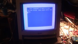
Last time I turned it on looking at it from a mirror and I didn't realize it was a bit tight as a horizontal opening. Thinking they were the adjustments I started to fix them, the vertical width works, the vertical position works, the contrast, brightness and color adjustment and the green button for, as well as volume horizontal position works.
But.....the adjustment of the horizontal width doesn't work! If I turn the potentiometer it has no effect on the image.
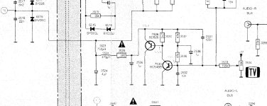
Attached is the difficult to understand result, but you can see two whiter lines on the sides that delimit the left and right edges and it doesn't go beyond that, I also enclose the area of the circuit that affects the horizontal width..... Only this remains problem but then the monitor can be seen very well.
Emanuel
I have replaced temporary capacitor 4,7uF250v with new 1uF250v same original, then have replaced temporary resistor with new inductance and the C2136 on the tube board, and turned on.
Last time I turned it on looking at it from a mirror and I didn't realize it was a bit tight as a horizontal opening. Thinking they were the adjustments I started to fix them, the vertical width works, the vertical position works, the contrast, brightness and color adjustment and the green button for, as well as volume horizontal position works.
But.....the adjustment of the horizontal width doesn't work! If I turn the potentiometer it has no effect on the image.
Attached is the difficult to understand result, but you can see two whiter lines on the sides that delimit the left and right edges and it doesn't go beyond that, I also enclose the area of the circuit that affects the horizontal width..... Only this remains problem but then the monitor can be seen very well.
Emanuel
Attachments
daver2
10k Member
Not so far to go then...
I would measure the voltage across the two fixed terminals of potentiometer 3534 - make sure the -27V is present.
Then measure the voltage from the wiper to 0V of potentiometer 3534. Make sure it varies from 0V to -27V as the potentiometer is adjusted.
Since you are having problems with resistors, capacitors and inductors I would check the following parts with the power OFF:
Inductors 5523 and 5524 are not open circuit or fried.
Fusible resistor 3526 is not open circuit or fried.
Capacitors 2524, 2526 and 2536 are not short circuit.
Next would be to measure the voltage across capacitor 2526 as potentiometer 3534 is adjusted.
Dave
daver2
10k Member
Great minds think alike (or sheep follow on) depending on your view!
Dave
Dave
Hugo Holden
Veteran Member
There was that recent thread I mentioned in post #92 where the inductor 5524 went O/C and prevented the width control working. If you look in that thread you will see I suggested replacing it with a better more reliable inductor from Miller.

(10 PCS) 07241-33 JW MILLER Fixed RF Inductors 470uH 10% | eBay
Fixed RF Inductors 470uH 10%.
www.ebay.com
Yes, cheched all component and same inductor 5524 of your post is opened!
Now ordered one because is it different to other one, but arrive next week.... probably working with a little resistor but at this point i prefer to replace later with original value.
Now ordered one because is it different to other one, but arrive next week.... probably working with a little resistor but at this point i prefer to replace later with original value.
daver2
10k Member
Sounds like a plan to me...
Dave
Dave
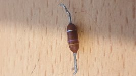
Just to complete the discussion, this inductor also does not seem to have burns, it just seems a little more swollen than the other, but it is also greater in value, my opinion is the porosity of the protective varnish which in my opinion with the 'moisture' ruins and oxidizes the internal filament.
Hugo Holden
Veteran Member
Basically these small dipped inductors are "undercooked" for the task in a deflection power stage . Wound from too fine a size copper wire, that is not very robust.Just to complete the discussion, this inductor also does not seem to have burns, it just seems a little more swollen than the other, but it is also greater in value, my opinion is the porosity of the protective varnish which in my opinion with the 'moisture' ruins and oxidizes the internal filament.
It is not that when they are new, they can't handle their rated power, but likely what is happening is that one mechanism or the other is causing a break in the wire. One could be internal flux residues where the copper wire was soldered to the leads, corroding through it. Or possibly, corrosion because the dipping material is porous, though enameled copper wire is fairly corrosion resistant, or possibly splits or internal cracks in the ferrite or the dipping material that break the wire. And it could also be over-spec'ing, in that the makers of the inductors claimed they were up to higher ratings and some years of thermal cycling did the damage. The reason they dip or coat them, is the fine wire needs mechanical protection. The type of Miller inductor I suggested has very thick & robust wire and doesn't need a protective coating.
However, I think the most likely failure mechanism is that when the VDU is switched on there are significant surge currents when the capacitors initially charge, easily 5 or 10 times the average running currents, and these peak currents can stress the fine wire in the inductor, eventually making it go open circuit, just like a thermally cycled fuse can go open. But when the VDU is running, a test of the rms voltage drop across the inductor would probably show that its power dissipation was inside the manufacturer's ratings, keeping the designers "happy". In any case, when I first saw this design of inductor in these VDU's, in this circuit location, in the power scan stages, I was surprised. Normally these sorts of small dipped parts work well in low power signal stages in the low voltage and low current B+ filter circuits.
daver2
10k Member
Dramatic music builds...
Dave
Dave
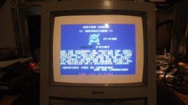
Ok, replaced and now horizontal size working perfectly, the monitor seems to be ok now, only the audio has a bit too much background noise even when the input is not present or if the screen have a white color predominant, like something high voltage is getting back into the audio, probably some other small capacitor in the audio section.
Attached the results and the second inductor replaced.
Attached the results and the second inductor replaced.
Attachments
Last edited:
daver2
10k Member
Sweet. Another one resurrected!
In a monitor, check all of the DC voltage rails and then the fusible resistors, inductors and capacitors.
By the looks of your faults, that accounts for most of them.
Dave
In a monitor, check all of the DC voltage rails and then the fusible resistors, inductors and capacitors.
By the looks of your faults, that accounts for most of them.
Dave
Yes, this truly from landfill to life, came from a flea market, then abandoned in my damp cellar, dismantled for 1 year with the pieces scattered around my room, and then brought back to life.Sweet. Another one resurrected!
The audio noise is actually a bit too annoying, but for now it's ok, you hear it well anyway, now I have to reopen it for a moment to reconnect the power LED.
Yes, before declaring a flyback or a power supply dead, I learned a lesson that for the 1084 it cost me 79 euros of flyback that arrived yesterday from Ireland, but it doesn't matter, I keep it for future replacement as I also have new HR7506 and HR7533.In a monitor, check all of the DC voltage rails and then the fusible resistors, inductors and capacitors.
Now I can try my hand at restoring my two Philips MSX and MSX2.By the looks of your faults, that accounts for most of them.
Dave