• Please review our updated Terms and Rules here

Commodore monitor 1084S-P and PHILIPS CM8833II

For exactly it's 8.1 volts on all three
Well this explains why the raster is so bright.

The video amplifiers are composed of a direct coupled transistor circuit for each channel, fed by a signal processor IC TDA3505(7640). The transistor pairs are configured in the Cascode arrangement, a clever invention to eliminate the effect of the Miller capacitance of the input transistor, by pinning its collector voltage to a fixed potential.

Most likely the transistor stages are ok, if the supply voltages to them are normal. Whatever the cause is, it is affecting the three channels equally.

The output of the IC are pins 5,3 and 1 each should have 3.6V on them. If not, something is upsetting the DC conditions of the IC, equally for the three channels. Check the IC's power supply on its pin 6, it should be 11.3V

The variable DC levels from the contrast and brightness controls are introduced to the IC at pin 20 , should be 1V (brightness) and on pin 19, 2V (contrast).
 
Last edited:
I just have a doubt now, but I don't think I was wrong, the flyback transformer has 3 output wires, one is the high voltage with the suction cup, then I have a black one and a red one, the black is thicker than the red one and I connected it to the focus socket, while the red one is connected to the neckboard and corresponds to G2, the doubt is that I have reversed these two? I should look into the 1084S-P1.
Likely, the black wire is for the focus (as it has a higher voltage than G2) and the smaller red wire next to it is likely for G2. The focus wire generally doesn't go onto a pcb connection, but directly into a hole in the CRT socket. The large red wire you have circled goes to the CRT final anode cap.
 
Well this explains why the raster is so bright.

The video amplifiers are composed of a direct coupled transistor circuit for each channel, fed by a signal processor IC TDA3505(7640). The transistor pairs are configured in the Cascode arrangement, a clever invention to eliminate the effect of the Miller capacitance of the input transistor, by pinning its collector voltage to a fixed potential.

Most likely the transistor stages are ok, if the supply voltages to them are normal. Whatever the cause is, it is affecting the three channels equally.

The output of the IC are pins 5,3 and 1 each should have 3.6V on them. If not, something is upsetting the DC conditions of the IC, equally for the three channels. Check the IC's power supply on its pin 6, it should be 11.3V

The variable DC levels from the contrast and brightness controls are introduced to the IC at pin 20 , should be 1V (brightness) and on pin 19, 2V (contrast).

Ok, the pin 6 is 11,3v, pins 1,3 and 5 i have 4,2 volt then about 2 seconds of powerup monitor, all three starts at about 2 volts then raise to 4,2 volt.
I'm uncomfortable now to measure pin 19 and 20, I'll try tomorrow by pulling the board out again.

For the flyback wire it's right connected, black on the hole CRT socket and red is soldered on the neck.

Thanks for now Hugo and Dave.... If this monitor will work again I will be able to combine it with a Philips MSX2, that would be very nice.

Emanuel
 
With the low cathode voltage, one would expect the 3.9k load resistors to be getting very hot and dissipating about 4 watts each. Can you turn on the set for one minute, then turn it off, wait at least 10 seconds and feel of those 3.9k resistors (eg part 3111) to see if they are very hot, or not.
 
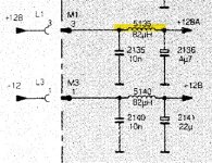
Not hot after 1 minute of power on but i have found this attached inductance seems to be opened, this is the +128A input to the cathodes transistors collectors.
 

Attachments

  • 128A inductor.jpg
    128A inductor.jpg
    57.8 KB · Views: 6
Last edited:
I'm going to bed, probably i have found the problem with this inductance, but now i don't have this spare parts, i need to buy, found kit of five on ebay.
 
I'm going to bed, probably i have found the problem with this inductance, but now i don't have this spare parts, i need to buy, found kit of five on ebay.
I was suspicious that the +128 was missing, affecting all three channels, That inductor is the problem. You can short that inductor out if you like, or just replace it with a resistor that has a similar resistance as the other 82uH inductor 5140, for now, for testing until the new part arrives, then the set should return to normal.
 
Agreed. The inductor (and the two associated capacitors) are there for filtering the +128V supply rail. Shorting the open circuit inductor out (or replacing it with an equivalent resistance) - as Hugo stated above - would be a temporary fix. You may get a bit of noise, but it would demonstrate that we were on the right track with the faulty component(s).

However, inductors are quite hardy devices and would only normally go open circuit if they were physically/mechanically damaged - or get fried by a high current... I would just check capacitor 2136 for a short circuit (or low resistance - high leakage) condition. Also, visibly check the inductor for mechanical damage and signs of burning. Much like a fusible resistor, inductors can be fusible wires!

Excellent work. See what I mean about measuring the DC voltages around the circuit first... Simple checks with a multimeter catch a high percentage of the faults without worrying about the fly-back transformer all the time...

Dave
 
Good morning :D, yes i have temporaly replaced the inductor with a 0 ohm resistors and the monitor lives again! :D :D :D
It need little regulations.

Yes dave, if you remember the 128v rail on power supply is a bit higher, (130,9v) but without 10ohm5W resistor connected and without the my distraction for not present capacitors, i try to mesuring again with all connected and loaded.
The inductor not have external sign of burning, nothig, late i try to post a photo of it.
I will check che capacitor 2136
 
For the C2136 when arrive the correct 1uF250v for video board i move the temporary 4,7uF250v to the tube board, but i think the inductor interrupted is for the dirt, dust and humidity inside the monitor when I turned it back on a year ago, on the tube and on the board I removed a lot of mould! If you remember in the first post I wrote that on this monitor I heard a little crackling when I turned it on at the time, this is probably the cause.

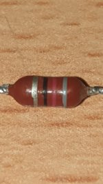
Attached photo of inductor 5135 removed.
 

Attachments

  • inductor 5135 .jpg
    inductor 5135 .jpg
    135.5 KB · Views: 3
Last edited:
That looks OK (not burned) so it must just have died a natural death!

I had a technician accidentally short out a +15V regulated 1A supply the 'far side' of an inductor and let out the 'black magic smoke'. The inductor was burnt beyond recognition!

Dave
 
Have a look at post #86 in this thread, the small inductors in these particular VDU's have a penchant for going open circuit:


They are really not ideal, with too fine a wire on these small dipped inductors. A better inductor, that is a more robust type , that has a bigger Ferrite core and much thicker wire, is like this from Miller, a more vintage design, but much more reliable:

 
Last edited:
Dave, what do you mean by noise, noise on the video image or intended as circuitry noise like whistling? Because it doesn't seem to feel anything in both cases, I still have to adjust the +128 but the pot is just under the neck of the tube, this monitor like the 1084S-P1 is really badly designed.
 
Electrical noise - making its way to the cathodes and 'imprinting' itself on the video image.

The +128V power supply (in fact, most of the supply rails from the power supply unit) are pretty crude - consisting of a half-wave rectifier diode (or, more correctly, a pair of diodes in parallel) and a 47uF capacitor 2451. This, in power supply terms, is pretty crude.

The +128V supply is fed to the PCB around the tube neck. The capacitor 2135 is a very low value - thus dissipating any high-frequency electrical noise. The 5135 inductor 'resists' any noise; with the capacitor 2136 acting as further DC smoothing.

If you notice, this supply is then fed to each cathode (in the form of a DC bias) via a further inductor and series resistor - thus providing further electrical noise suppression.

As this voltage is used as a DC cathode bias, any electrical noise on this supply would result in the random fluctuation of the electron beam current, so you could see this electrical noise imprinted on the video picture. These inductors and capacitors are used to reduce this potential issue.

Hope that makes sense?

Dave
 
OK, at the moment i don't have noise, but if possible when hot, but i have turned on monitor for max 2 minutes for the two temporary component.

The capacitor arrive tomorrow, and inductance i don'know.......probably in 2-3 days, but this monitor have a very very nice screen quality, best of 1084S-P1, and is the same tube and board!
 
>>> OK, at the moment i don't have noise.

That's fine. I don't think Commodore would have installed components for no reason.

Of course, these monitors have to work under scenarios where radiated and conducted electromagnetic interference is present.

It is likely your home is relatively 'quiet' (electromagnetically) so the monitor is not probably subjected to the electromagnetic noise that is could be under the requisite Standards.

For the same reason people discard the WIMA filter capacitors found in the mains input of most equipment. They go BANG in vintage equipment and, therefore, removing them doesn't prevent the equipment from not working. However, the equipment would not pass the EMC/RFI qualification testing if it was ever subject to it...

Dave
 
>>> OK, at the moment i don't have noise.

That's fine. I don't think Commodore would have installed components for no reason.

Of course, these monitors have to work under scenarios where radiated and conducted electromagnetic interference is present.

It is likely your home is relatively 'quiet' (electromagnetically) so the monitor is not probably subjected to the electromagnetic noise that is could be under the requisite Standards.
yes without my sons :D

For the same reason people discard the WIMA filter capacitors found in the mains input of most equipment. They go BANG in vintage equipment and, therefore, removing them doesn't prevent the equipment from not working. However, the equipment would not pass the EMC/RFI qualification testing if it was ever subject to it...
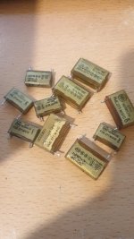
yes the RIFA caps...... :D i replace with new one poliester caps always! attached part of my collection :D


Attachments

  • rifa.jpg
    rifa.jpg
    186.8 KB · Views: 4
So we wait for replacement components...

I am also waiting for components to finish a project...

Let's wait together!

Dave
 
yes without my sons :D


yes the RIFA caps...... :D i replace with new one poliester caps always! attached part of my collection :D
The original Rifa X2 caps are metalized film on paper. As they age two things go wrong. The film is eaten away and the uF value drops, if that was all that happened, it would be ok, except when they are used as series dropper devices in small appliances and the appliance dies. The main issue is the thin walled plastic brittle casing cracks. This lets in water vapor and the paper expands in volume. This widens the cracks and the capacitor starts to physically swell up. Later it smokes. So despite the fact they are supposed flame/fire proof, they still burn.

If you replace these with standard Polyester types, it is not a good idea, unless they are X2 safety rated, as they then pose a fire risk because they don't have the required open circuit failure mode. Though, if the capacitors are 1500V to 2kV rated, the chance of them failing is very low for a standard polyester or polypropylene type in a line supply. In the "old days" before modern X2 caps were invented, wax paper types were placed across the line terminals. Usually though they were sealed in a protective metal canister to obviate fire risk and at least 1kV DC rated.

I have told this story before: Many years ago I was sleeping in a room that had an electric Singer Sewing machine. In the foot pedal it has a Rifa X2 capacitor as a snubber across the control element and the machine was on at the wall plug, it had no pilot light. The capacitor in the pedal shorted out suddenly in the middle of the night and the machine came on at full speed waking me up in a dazed state, wondering what the heck was going on. Later I realized what a silly idea it was to have these capacitors, as sometimes people do, as snubbers on relay & switch contacts that control industrial machines. It could lead to a very bad accident.
 
Last edited:
Back
Top