daver2
10k Member
There are two (2) different issues here - and you need to eliminate one of them before you can start to see the wood for the trees.
The two separate issues are:
1. The character generator ROM and/or circuitry.
2. The video RAM itself.
In order to make any headway with item 2 you really need to bottom item 1 first.
You can do this by removing the video RAM and 'forcing' logic 0 and 1 signals onto the RAM outputs via low-value resistors. This will permit various characters to be generated that would occupy the whole screen image.
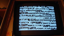
The character screen presented in post #440 is still not 'random' though. For example, there are no inverse video characters (assuming this is a 'power-up' screen display).
Dave
The two separate issues are:
1. The character generator ROM and/or circuitry.
2. The video RAM itself.
In order to make any headway with item 2 you really need to bottom item 1 first.
You can do this by removing the video RAM and 'forcing' logic 0 and 1 signals onto the RAM outputs via low-value resistors. This will permit various characters to be generated that would occupy the whole screen image.
The character screen presented in post #440 is still not 'random' though. For example, there are no inverse video characters (assuming this is a 'power-up' screen display).
Dave
") !
!