• Please review our updated Terms and Rules here

Commodore PET 4008 with strange issues?

Well,

Over on another thread we are currently working on a PET 2001. The address multiplexer logic is very similar for your PET (no CRTC) and the 2001. You may learn enough by reading that thread and apply it to yours?

Dave
I'll give it a look, thanks
 
Well, I picked up my scope again and thought I'd give fixing the video a go again.

Here's a thing...
Should LSD7 be a constant 5V?
I noticed that it runs from UG9 to the latch UF9 connected to the VRAMs. The signal at UG9 pin 11 (LOAD SR, I presume this is the signal to load a value into the VRAM being static?) is a waveform of some sort, pulsating between 5V every ~1uS - I don't know if that's normal behavior but it doesn't strike me as immediately wrong.
I'm guessing therefore that some signal logic happens in UG9 and sends the resultant signal down to the latch through LSD7 - this is just an educated guess, mind, but I presume that line shouldn't be a constant 5V?
Perhaps an internal short in UG9 from my accident?

Cheers
 
Having a static +5V on SD7 would not usually be normal - but it depends on what has been stored into video RAM of course...

You are also looking at the signal 'backwards'.

Data is sourced from the video RAM from F7/11 (SD7). This is connected to F9/13 (a latch).

The signal is latched by F9 and exits on F9/12 (LSD7) and enters G9 on pin12.

Go back to F9/13 and see if that is +5V all the time or not...

Dave
 
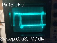
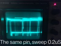
I've checked F9/13 and, well...
There's a signal, I can't quite get a lock on it with my scope being as it's so messy (and goodness I tried, even on auto it can't find the trigger pulse) that fluctuates within a roughly 5V range, though most of it seems to be within 0-4V. I've attached the best pictures I could get.
I'm certain that the issue here is my use of the scope. Either way, it's at least not a constant 5V, but it can't be a hugely clean signal either.
IMG_20241115_205536__01.jpg
IMG_20241115_205734__01.jpg
 
Also, thank you for correcting my logic flow assumption through the latch. Frankly I'm still in such early days with 8-bit hardware of this era - with the 64 I could fairly know this IC controls the RAM for example, while here there's so much more complicated a process for everything. Alas the service manual is painfully vague on the nitty-gritty of each IC's function, so I really do appreciate that.
 
I assume you have a regular constant clock on F9/11?

F9/1 should be a permanent 0V.

If you still get a constant +5V on F9/12, then (on probabilities) F9 is probably faulty.

Are there any more outputs from F9 that appear 'stuck' yet have inputs on F9 from the video RAM?

Dave
 
I just tested the inputs and latched outputs of F9 (I get it now!) and ah.
It seems I'd gotten our hopes up falsely - there is in fact not a constant +5V on LSD7, I had my scope trigger set wrong. Damnit.
Well, I supposes it saves a wild goose chase, but it's back to the drawing board. The signals in and out of F9 seem alright at a glance.
 
Uh, Uh, Ok...
I decided this morning to test E7 and E8 being as they shared a data bus with the VRAM.
I fired up the PET expecting the garbled mess of "shimmering" characters that it started doing recently.
Nope. The display has reverted to exactly how it was when I very first started working on this pet.

Greetings all,

I'm new here, but thought this might be the right place to ask for any kind advice in fixing a PET I acquired recently. I've attached several images of what occurs on boot having cleaned the board and sockets to hell and back.

I suspected initially that the issue was VRAM, so I swapped the original MOS MPS 2114s for two NEC UPD2114LO-2s that I've used with no issues in several C64s. As attached, the weird garbled mess on the screen is different, and swapping the new VRAMs around seems to change which characters are in what position; otherwise (without swapping positions), they are the same on every boot.

There's no familiar beep / chime when switched on, and having removed the 6502 seems to have absolutely no effect on what's displayed.
I've also checked the voltages on each power line and they correspond to the diagrams, give or take ~10%. The traces all seem visually spotless too.

Don't suppose anyone has any advice on what could be at fault, or what to check (and how, I am a little dim).
Thanks again!
^ If you notice the "after VRAM swap" image of the original post, it matches identically the display currently.
Is the PETTEST EPROM dead?

I did test some capacitors that looked slightly larger than others with a multimeter (all just about within +-10%), if that killed my EPROM I resign!

I also blew the dust off of my board in case a hair or somesuch had fallen on the board (noticed that before testing so to be safe I cleaned it).

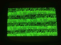
The current display of the PET:
IMG_20241116_124543.jpg

EDIT:
I was just about to post this, but tested it again one more time. It did the shimmering thing and displayed some slightly different characters.
Restarted it. No more shimmering. The inverted luminance colours are now more correct:

EDIT 2:
Trying to get a photo of that, it's back to how it was at the start of this message. What the deuce is this thing doing...?
I'd thought it might be a capacitor problem because I left the machine a little while to write out this message. I did so again and no, back to the start of the message (image above)

I am... lost for ideas now.
 
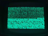
Aha, I left it a little longer, unplugged the board to check for hairs etc that might short it or something equally daft.
Here's the state as described by "EDIT:":

IMG_20241116_131252.jpg

(The checkerboards are the "shimmering" characters)
After restarting it, it returned to a similar state as in the previous message, except with different characters in each position.
Could this possibly be a power issue if it changes after being restarted...?
 
It could be a power or reset issue.

Note, you will need to leave the PET for a while after switching off before turning on again - unless you have fitted a manual reset button.

Always check CPU pin 7 (SYNC) to see if the CPU is actually executing instructions.

Dave
 
Did you perform the tests described in my post #95 correctly? Especially moving the resistors around between 0V and +5V to test all combinations of each data bit being high and low? If you started off with 11111111, you could then move one resistor in turn from +5V to 0V and retest, e.g. 11111111, 01111111, 00111111, ..., 00000011, 00000001, and finally 00000000.

At each step, the screen character should corresponding to the correct character code for the bit pattern, and the screen contents should be completely stable.

If you are not sure which character code is correct, post a photograph at each step and I will check.

If that is correct, then the problem is in the video RAM or backwards...

Dave
I performed the test before noticing this behaviour. I left my resistors in storage when moving hotels, but I can give it another go tomorrow. Last time I only ran all of them into +5V or 0V, not one at a time - I'll give that a god this time.

To ensure it is/isn't a reset error, roughly how long would you leave a pet before rebooting to be safe?

(I'll check the CPU too while I'm at it)
 
Last edited:
This may be something (it may also be entirely me using my scope wrong, as ever!)

I checked the SD buses and data buses from E7&8 in hopes to find something catastrophically wrong there and walk away joyous.
I couldn't really lock onto the signal brilliantly well, but what I saw looked fine. Likewise Video Latch and LOAD SR / NOT LOAD SR, and possibly TV RAM R/W.

This is pure guesswork based on how the waveforms look! I have no reference for that.

This got me looking into the address bus, which seemed fine, again.

While poking around there, however, I was reaching the end of my will to work on the PET today when I decided on a pure whim to test H2, as far as I can tell a NOT gate.
H2 pin 2 should be NOT pin 1, likewise pins 13&12, 3&4... respectively as per the diagram. The input signal, unless my scope is triggering wrong with no positional adjustment and a fixed trigger level, was the same as the output.
Again I might well be using the scope wrong, but it definitely seems to be the case.
I tried I1 as a sanity check, as that seems to be the same type of NOT gate (exact same IC) but used for the oscillator. Same result - no noticeable difference to the waveform on any pins.
Sure, both ICs failing is a long shot, but I suppose it makes some degree of sense that if one is likely to fail another may well too.

I recall at some point (goodness knows what reason) earlier I swapped out A3, which is exactly the same IC and the spare appears entirely functional (though it seems to only NOT constant signals so...).
Honestly the behaviour of this PET is now so absolutely unpredictable that I can't really say what issue I'm chasing at all (I'm tempted to even re-cap the board just because of how variable it is after each time you turn it off for a few seconds, but I know that's unecessary stress on the board so holding off until the point of sheer desperation).
Therefore, if you think there's any chance these ICs are at least partly at fault, I'd more than gladly swap them and see what happens - I really cannot find any other obvious issues even after a bit of digging and testing with the scope.

Given my painfully little experience with PETs, it's hard to know if a signal I'm seeing is actually good or not, but even just taking a guess I don't think most of what I've seen is faulty.
Cheers folks!
 
While poking around there, however, I was reaching the end of my will to work on the PET today when I decided on a pure whim to test H2, as far as I can tell a NOT gate.
H2 pin 2 should be NOT pin 1, likewise pins 13&12, 3&4... respectively as per the diagram. The input signal, unless my scope is triggering wrong with no positional adjustment and a fixed trigger level, was the same as the output.
I assume by saying a NOT gate you mean an inverter gate, where you are expecting the output to be in inverted version of the input.

If the wave you are looking at is a square wave (or close) on a single channel of the scope, it will look the same/similar if it is inverted or not, because inversion also simply phase shifts the pulse chain by 180 degrees so it will look the same, but you would spot it with a duty cycle well away from 50%.

The way to tell if the inverter gate (and many other gates too are working) you put the gate input on channel 1 of the scope, and lock onto that (or the output is you so choose to put the other channel on inputs). Then with the scope in dual channel mode (usually better in Chop mode than ALT) connect the gate output to channel 2 and you should see the waveform inverted with respect to channel 1.

You may have already been doing the above, but I thought I'd mention it just in case.

One other trap to fall into is that many scopes have an Invert option on channel 2, if that is left accidentally on, that can cause some confusion.
 
Last edited:
As Hugo has said, it all depends upon what your trigger is.

If the trigger is (say) a LOW to HIGH condition, then looking at the input of an inverter will look the same as the output.

In this case, use channel 1 on the input as the trigger and channel 2 on the output.

We have seen the same issue with the Q and /Q outputs of a flip-flop. They both look the same when you look at them with a single channel [sic]!

Unfortunately, randomly 'poking around' with an oscilloscope probe generally yields nothing... Just occasionally (very occasionally) you find a 'stuck' signal. However, in my experience, a 'stuck' signal usually results from a fault earlier on in the circuit, but it can be used to locate something unexpected, especially if you are at a loss...

Did you perform my test as I asked?

Dave
 
Aha, that seems like a highly logical approach. I'll test that later if I brought a 2nd probe with me. I'd expected their phase to be out by 180° (that's a much better way to explain it yep) but the trigger I believe was on a rising signal so it may well be alright and I'd just been measuring wrong.
 
Back
Top