• Please review our updated Terms and Rules here

Commodore PET restoration help needed

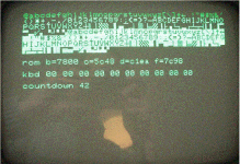
Alright, Removing the 2nd memory bank, nothing happened. So i replaced all the chips from the 1st row with the chips of the 2nd row, and now the computer would pass the test on to the next stage. The diagnostic program now registers 16KB of RAM and continues the test. The final test finishes with a "0............ pass 000001."

what i did notice is when it lists the checksums for the ROMs dont really match up with the ones from the documentation of daves diagnostic program.

But i thought, what the hell, lets put in the original ROM chip and start it up, sadly the screen remains completely blank.

SkyCaptain
IMG_2534.gif
 
... what i did notice is when it lists the checksums for the ROMs don't really match up with the ones from the documentation of daves diagnostic program. ...
Are the ROM checksums the same every time or do they change each time you run the test? Often a bad ROM will change which is a sure sign of it being faulty.
 
The First number stays but the other change. So i guess that means the ROM's are busted?

I guess i will try to order an other 16K of RAM and the parts to build the adapter to program 2532 EPROMs with the 2732 settings. For that purpose i found this post here:
http://www.simonsdialogs.com/2015/08/tms-2532-eprom-adapter-one-byte-every-50-ms/

Dave_m mentioned that "Note that an adapter to burn a 2532 on the 2732 setting requires the adapter with an isolation diode to protect one of the pins from the 25V.". The link i showed uses no isolation diode. Am i missing something again?

SkyCaptain
 
My PETTEST constantly computes the checksum so you can see if the ROM contents are changing. They are in your case, so it is highly likely some if your ROMs are intermittently faulty. A number of people (that have bust ROMs at any rate) have found this feature worth its weight in gold!

ROMS not working == PET not working!

By the way, leave the memory test running for more passes than just one...

Dave
 
Dave_m mentioned that "Note that an adapter to burn a 2532 on the 2732 setting requires the adapter with an isolation diode to protect one of the pins from the 25V.". The link i showed uses no isolation diode. Am i missing something again?

Sky,
Wired like that, the 2532 may program, but will not verify. To verify, the Vpp pin 21 of the 2532 must be at +5V. The adapter connects it to pin20 of the 2732 which will switch from +25V during programming to ground to verify. Does anyone have the proper adapter which will program and read on the 2732 setting of a programmer?

I would think 2 diodes would work. Both diodes with the band end on both wired to pin 21. The other ends wired to vpp of the programmer and +5V of the programmer. The 2532 gets vpp when programming and 5v when in verify. The programming will be .6V low but that shouldn't be an issue. The 5V is just a logical High so the diode is fine. You might want to use a 1N4004 or similar as the current spike can be high when the vpp goes high.
That is if I understand Dave's question right.
Dwight

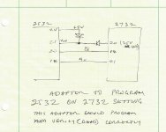
Yes, Dwight you beat me to it. I couldn't find the diagram on the web so I sketched one. Pin 24 must be Vcc on both sockets. Did I get it right?
-Dave
2532 EPROM Adapter1.jpg
 
We had the basic idea. I still think the vpp diode should be a little more than a 1N4148 or 1N4149. I'd still use a 1N4001 ro 1N4007 depending on availability and cost.
Dwight
 
Thanks Mike, that was the write up I was looking for. I had forgotten that it was written by our friend Giovi who fixed his machine with only a DVM and a soldering iron. What a guy, he never gave up.
-Dave

Yeah, we've met some folks on here with amazing patience and persistence, way more than I can claim, and when all was said and done, almost all of them were rewarded with a working PET. Very satisfying...
 
Hey Guys, How has everyone been? I have finally built my adapter, and think im ready to Burn some ROMS.
First i think i want to make it as original as possible, and i think this machine was running BASIC 2 originally.

So I read through the documentation over at zimmers, and it i have selected the following 4 files (I selected the business keyboard for the edit ROM over the "normal" one as I assume the normal one is that calculator type keyboard):

basic-2-c000.901465-01
basic-2-d000.901465-02
kernal-2.901465-03
edit-2-b.901474-01

Is this correct?

SkyCaptain
 
Hello SkyCaptain,

from the photo in your initial post i can clearly see you are having the same type of Keyboard as i have which is the normal one. So for the Edit ROM you should use this file:
edit-2-n.901447-24.bin

The other ROMs are correct!

Good luck!
best regards

Denis
 
I agree, that looks like the 'normal' keyboard.

The 'business' keyboard doesn't have the graphics symbols on the keys (after all, no one will want to play games and do programming on a business machine; will they).

The 'calculator' style keyboard is known as the 'chicklet'.

You can see all three of them here http://www.6502.org/users/andre/petindex/keyboards.html.

Note that the text corresponding to the keyboard photograph is to the left or right of the photograph NOT above or below!

Dave
 
Yeah. The chicklet keyboard and the normal/graphic keyboard are compatible and interchangeable electrically. Not physically of course but the computer can't tell the difference.

The business keyboard has a smaller 3x4 numeric keypad, the others have a 4x5 numpad.
keyboards.JPGOne of each
 
Hey again, so its kinda weird, the adapter built, the EPROM burner gives me a "VPP over current protection" "External short or IC socket reversed". But the EPROM burner does read the chip, and can verify (that its empty) so im not really sure what i did wrong with that adapter.

Im gonna start by building a second one and trying to do the soldering even cleaner. But i do not think thats the problem. Maybe my 2532A-45jl is different or i need an other 2732 setting in my program.

SkyCaptain
 
Can you remind us exactly what your devices are (manufacturer, make and model) and what you set in your EPROM programmer?

VPP over-current usually means there is a short circuit on the VPP line, or you are trying to program the device with too high a VPP voltage.

Reading the device usually takes place at 5V not 21V/25V. Although verifying should occur at VPP - but that may not be valid for low-end programmers.

Just checked. The Texas Instruments 2532 is a 25V VPP part. The Texas Instruments 2532A is a 21V part (assuming your part is manufactured by TI of course). Ensure your programmer is trying to program it at 21V...

Dave
 
A dead EPROM will usually read as unprogrammed. a few days a go, I installed one upside down. I wish the different manufactures would put the labels on a consistent end. Sometimes it is on the notch end and others it is one the opposite end. It only takes a 1/4 of a second to blow a bonding lead.
Years ago, when I worked at Intel, we had access to a wire bonder. Twice when we blew EPROMs, we'd use a hot plate to remove the window and bond a new wire. With the cover off, the chip may have a limited life with exposure to outside contaminates but it was good enough for use to finish what we were doing and order a new one from supplies. The ICs were robust but the bonding wires were more like fuses.
The programming voltage to high would do the IC in though. I had a couple 2732As that I was using on my current project that only took about 10 program passes before they quit working. That is life sometimes. I ordered some new ones that have been working fine except the one I installed upside down.
Dwight
 
Back
Top