• Please review our updated Terms and Rules here

Converting CBM 8032 PET to switching power supplies

Ok. So the installation could be in the two ways that I send in the files, right?
Would option 1 and option 2 work the same?
 

Attachments

  • opcion 1.jpg
    opcion 1.jpg
    79.8 KB · Views: 7
  • opcion 2.jpg
    opcion 2.jpg
    81.6 KB · Views: 6
Ok. So the installation could be in the two ways that I send in the files, right?
Would option 1 and option 2 work the same?
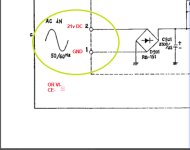
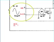
As I mentioned in post #19, the bridge rectifier can prevent reverse polarity accidents, because the apparatus will work regardless of which way you hook up the DC source. This adds a level of safety for all the IC's on the pcb, along with the analog regulator protecting them too.

Just using a single series diode will also prevent a reverse polarity accident, but in that case it will only work when the correct polarity is applied. The only disadvantage is heat generation in the diode/s which is the product of their forward voltage drop and current. Using Schottky power rectifiers can cut those losses nearly in half compared to a standard silicon rectifier because their forward voltage drop is lower.

I'm pretty sure that in at least one case of a PET repair we have seen on the forum, where there were multiple failed IC's in the circuitry fed by one of the 5V regulators, that it was either due to an improvised 5V power supply being inadvertently connected to it in reverse, or an accidental input output short of the 5V regulator with debris on the workbench.

Generally, with original hardware, it is fairly difficult to have something like a reverse polarity accident because the connectors only fit one way. It is when modifications are made, like adding non-standard power supplies that things like over voltage and/or reverse polarity accidents can destroy multiple IC's on a computer mobo, so a lot of caution is required when doing it.

Also, most SMPS's designed for computer use, generally have under and over-voltage protection and over-current protection, with output voltage window monitoring and shutdown, or other systems with SCR crowbars. Generic SMPS's are not often gifted with the extra protective systems which are helpful in protecting pcb's with multiple IC's. In general, when I see projects where original computer supplies, especially analog ones, or any type, are replaced with non-standard supplies, especially ones not designed for specific computer use, it makes me nervous, because of the range of things that can can wrong, not anticipated by the people making the modifications.

On the other hand, analog supplies don't generally have an over-voltage failure mode (it can happen in rare cases with shorted pass transistors), unless say you plugged a 115v unit into a 230V source. Manufacturers knew about this obvious mistake, that is one reason why there is primary fusing on the transformers and the analog regulators which have output voltage clamps, normally will protect the IC's in the event of that accident. In the SOL-20 they also included an SCR crowbar circuit.

One relative advantage of many modern SMPS's is that they are universal voltage input, and that is helpful.
 
Last edited:
Yes, the video board by the PET can pass the 21VDC through its full wave rectifier with minor voltage drop and drive the the voltage regulator chip which outputs the required +18VDC.
See Video board schematic http://www.zimmers.net/anonftp/pub/cbm/schematics/computers/pet/8032/321448.gif

Just noting the smaller 9" monitor option only takes 15V


I designed this mod for the larger 12" monitor that takes 21V
 
One thing to consider, replacing the AC supplies with regulated DC ones, the DC value you ideally want is about 2.5v higher than the analog regulator's output voltage. This keeps the heat in the analog regulator as low as possible.

In the case of the 9" PET VDU, that is very important because in this one, with the system they had, with the AC voltage feed, bridge rectifier etc, they pushed the thermal dissipation in the 7812 regulator to near maximum and it does require a good thermal bond to the heat sink, or the 7812 goes into thermal shut down. In the other PET VDU's they shunted some of the current across the voltage regulator with a power resistor and the regulator output voltage was higher too.

Ideally in the 9" VDU, no higher than about 12 + 2.5 +1.2 = 15.7 V DC (as a substitute for the AC) should be fed to it, the 1.2V being the approximate voltage drop of two diodes in the bridge rectifier which conduct with the DC feed.

The same basic principles apply to the 12" VDU, if it was to be powered by a DC feed so as not to overheat the analog regulator in it.

However, the terminal voltages referred to on the diagram you posted for the transformer are rms AC voltages. The peak value that you get from those out of a bridge rectifier is 1.4 times that, less the 1.2V loss in the bridge on each half cycle. So 15V rms will give about (15 x 1.4) - 1,2V = 19.8V DC.

In practice though the average value is a little lower because the line power sine wave is often rounded off a little at its peaks (ironically due to the loads from many SMPS's) and the voltage falls (ripple) between charging peaks. Generally it is arranged so that the filter capacitance is large enough to keep the ripple below a volt or two.
This higher range value is required in the analog regulator supply input to allow for fluctuations in line voltage. If the voltage troughs down too low between charging peaks, ripple voltage can break through to the regulator's output. Of course using the SMPS to feed the analog regulator results in a cooler running regulator, than usual, if you set the regulator's input voltage about 2.5V higher than its output voltage.
 
Last edited:
Back
Top