• Please review our updated Terms and Rules here

Converting CBM 8032 PET to switching power supplies

hideehoo

Experienced Member
Joined
Aug 4, 2015
Messages
54
Location
Prior Lake, MN
Picked up a 8032 with bad transformer a while back, my son posted about it here.

http://www.vcfed.org/forum/showthre...e-CBM-8032-Transformer-Problem&highlight=8032

Primary winding is open circuit, didn't see a thermal fuse anywhere. Bottom line is fixing the transformer seems like a non-starter, exact replacements are unobtainium and likely failure prone during the shipping process (old and heavy), and individual transformers of sufficient amp ratings are expensive and I'm not sure I can actually fit them all given the all the different voltages needed here at sufficient amperage.

So, as much as it pains me to hack this up, I'm thinking of going with an +18V AC-DC SMPS to feed the monitor, and then some DC-DC buck converters (probably xl4016 based) downstream to get +12V and +5V, and finally a LM2662 based negative converter to get the -5V for the DRAM. Total cost via my favorite Chinese vendors is around $20. Judging by the max current delivery capacity of the existing linear regs, I'm guessing a 18V 10A supply, two 8A bucks for +12V and +5V, and finally 200ma for -5V should easily do the job, even factoring in Chinese amp ratings :)

Will need to pull the linear regulators, some of the existing buffer/storage caps (to prevent inrush surge currents at power up), and the rectifier bridges so I can reuse the transformer connector block to make things look somewhat tidy.

Thoughts? I feel dirty already, but a working computer in this case seems better than one just collecting dust.
 

MikeS

Veteran Member
Joined
Dec 23, 2005
Messages
7,510
Location
Toronto ON Canada
If you're going to bypass the regulators anyway why not just use an AT supply with a boost converter for the monitor?

On the other hand, why not just leave the PET board as is and set your boost/buck adapters to deliver the original voltages (+9, -9 and +16) to the original connector and ~21V to the monitor? DC voltages will just pass through the bridges, albeit with a little voltage drop.

m
 

dave_m

Veteran Member
Joined
Feb 2, 2009
Messages
3,616
Location
Southern California, USA
On the other hand, why not just leave the PET board as is and set your boost/buck adapters to deliver the original voltages (+9, -9 and +16) to the original connector and ~21V to the monitor? DC voltages will just pass through the bridges, albeit with a little voltage drop.

m

Mike's solution also has the benefit of producing the +9V required for the cassette motors. See Schematic sheet 3.
 

hideehoo

Experienced Member
Joined
Aug 4, 2015
Messages
54
Location
Prior Lake, MN
Mike's solution also has the benefit of producing the +9V required for the cassette motors. See Schematic sheet 3.

Good point on the +9VDC and the tape drive, was curious why that was sent along on the power schematic, http://www.zimmers.net/anonftp/pub/cbm/schematics/computers/pet/8032/8032029-11.gif

I thought about leaving all the linear regs in initially, but sort of felt wrong heating them all up with nice regulated DC input. That being said, would be a lot easier and keeps things more "original". Maybe I'll give that a try first, pretty simple to wire up. I'm just always paranoid about killing the triple voltage DRAM of this era. Seen lots of lower memory issues on Spectrum ZX's when the +12 and -5V regs go bad and only +5V is left powering them.

KC9UDX, regarding using individual transformers again, getting the three of them (21VAC, 9-0-9 18VAC center tap, and 16VAC) at adequate amperage (there's over 5A's of potential +5VDC regulator on my board between the main board and the 64K RAM expansion card), taking into account the Hammond tech notes and the massive smooting caps (especially on +9VAC), just didn't seem cost effective looking in either the Hammond or Triad Magnetics options from places like Mouser or Newark.

http://www.hammondmfg.com/pdf/5c007.pdf

The original transformer is/was a beast.
 

hideehoo

Experienced Member
Joined
Aug 4, 2015
Messages
54
Location
Prior Lake, MN
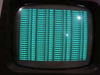
It's alive!

It's alive!

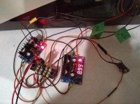
Ghetto rigged it all up.

IMG_20180930_223816126.jpg

+21V DC feeding the monitor through the rectifier bridge and rest of the buck converters.

+16V DC feeding the +12V regulator through the rectifier bridge.

+9V DC feeding the +5V regulator directly, bypassed the rectifier bridge since there's an exposed pin on the power connector for it. No point in heating some diodes.

-9V DC feeding the -5V regulator through the rectifier bridge.

Came right up, drawing 1.7A on my lab power supply.

IMG_20180930_223828775.jpg

All the board voltages look good, ran fine for about 30 minutes while my son got the disk drives working. Now to order a 24V supply that will fit in the case and 3D print some mounting brackets for this mess and new input switch (with fuse) on the back.
 

hideehoo

Experienced Member
Joined
Aug 4, 2015
Messages
54
Location
Prior Lake, MN
Thingiverse link is in the blog post, but here it is again.

https://www.thingiverse.com/thing:4801074

These were quick a dirty designs my son did. They work fine, but the Mean Well PSU mount could use a little more meat around the mounting holes and extra standoff's on the two corners to better support the PSU. I'll try to dig up the AutoDesk files and upload them also if anyone wants to modify them in the future.
 

ricsne2010

Member
Joined
Apr 4, 2022
Messages
47
Location
Nevada
Do you by chance just tap the +21V DC to the monitor using the exising power leads that came from the old Transformer? I was under the impression that the voltages coming from the Transformer are AC and not DC....

Thanks!
Cheers
Rich
 

daver2

10k Member
Joined
Jun 19, 2012
Messages
10,042
Location
UK - Worcester
Yes, voltages coming out of transformers are AC - but the AC voltage is then rectified, smoothed and regulated down to the desired voltage on the PET main logic board.

In principle (but there are the odd exceptions of course) you can feed a stabilised DC voltage into the PET board in place of the AC voltage. This will still use the rectifiers, smoothing capacitors and voltage regulators on the PET main logic board of course. This would only be of use if the transformer was dead and you couldn't obtain a replacement.

You could also bypass the onboard rectifiers and voltage regulators and feed the correct regulated DC supplies in instead. Alternatively, you could remove the onboard regulators and feed external regulated DC power directly into the output (and GND/0V) connections of the regulators. These options are a little bit 'abhorrent' to me - but (if it was the only way to resurrect a dead PET) I would consider it as a last resort...

Of course, the monitor supply has its onw bridge rectifier and voltage regulator.

Dave
 

ricsne2010

Member
Joined
Apr 4, 2022
Messages
47
Location
Nevada
Yes, voltages coming out of transformers are AC - but the AC voltage is then rectified, smoothed and regulated down to the desired voltage on the PET main logic board.

In principle (but there are the odd exceptions of course) you can feed a stabilised DC voltage into the PET board in place of the AC voltage. This will still use the rectifiers, smoothing capacitors and voltage regulators on the PET main logic board of course. This would only be of use if the transformer was dead and you couldn't obtain a replacement.

You could also bypass the onboard rectifiers and voltage regulators and feed the correct regulated DC supplies in instead. Alternatively, you could remove the onboard regulators and feed external regulated DC power directly into the output (and GND/0V) connections of the regulators. These options are a little bit 'abhorrent' to me - but (if it was the only way to resurrect a dead PET) I would consider it as a last resort...

Of course, the monitor supply has its onw bridge rectifier and voltage regulator.

Dave
Good info for sure.... I had not jumped head first into the wiring diagrams of the monitor.... so if feeding the monitor +21 VDC is the same theory as the rest of the board, then I would be fine...

From the looks of it, my transformer might be in good shape... so time to figure out what else "down stream" is going on....

Thanks for the info!

Cheers
Rich
 

ricsne2010

Member
Joined
Apr 4, 2022
Messages
47
Location
Nevada
No problem Rich.

What are the patient’s symptoms?

Dave
At present,

the 4016-12 Machine exhibits the following issues:

1) No power to the transformer (resolved by removing the old power input plug, switch, and fuse with an after-market assembly NIB)

2) When all hardware is connected (power, keyboard, etc) - upon power up - no chirp, no video.... just a blank stare.... no indication of life if any keys are pressed

That is as far as I have got (except for the assistance you have provied in a seperate thread regarding the Transformer question....)

I plan to reconnect the motherboard to the "verified" working transformer and test the Capicators as indicated in the other thread (see link below)


As always, thank you so much for the extra eyes and assistance on this one!

Cheers
Rich
 
Top