Hugo Holden
Veteran Member
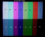
Out of curiosity, do you have any software that runs in the 4x resolution B&W mode? I'm wondering what the 128x128 pixel mode looks like. (Did anything actually use it?) Mainly I'm wondering about both modes... is the active video field 256 lines out of the possible 262 in height? I imagine a fair bit of it must get cut off in the overscan on a typical CRT, which leaves me wondering what the "effective" on-screen pixel resolution is. In color 64x64 mode are the color pixels three pixels tall (192 lines) or four (256)? I assume it must double-scan the 128x128 in the 4x mode... or is that rendered as just a "letterboxed" strip?
Since you mentioned the Matrox ALT-256... is there much software out there for that? I was kind of wondering if I might be able to emulate it without too much trouble with the video processor idea I've been working on. According to the manual it works by setting individual pixels by receiving X/Y/on-off coordinates via I/O ports, there's no "direct memory access"? Is there any delay in this process with the card, or can the CPU ram pixels in at full speed with no wait states?
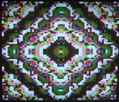
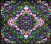
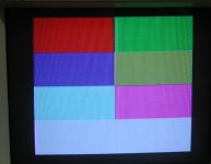
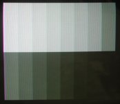
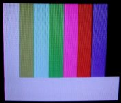
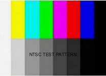
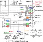
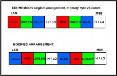
In the x4 mode the size of the image stays roughly the same size, it doesn't go letter box looking. I will make an image file for that and take a photo.In this mode you can selectively deactivate R, G & B, and this is used to help the initial setup of two of the potentiometers on the board.
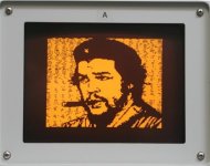
The image doesn't extend near the full raster width or height, there is a good gap around it on the monitor I'm using which has the usual small amount of raster overscan.
Yes, in the ALT-256 you cannot get the image data out of its RAM after you put it there. But in the ALT-512 you can, there is a register to do it. For that I had to write a program to extract it and save it to a disk file. Matrox did make an elaborate program called MTXgragh, but I have not assembled and tested it yet. Here is the article I wrote on the 256 and 512, I'm doing the same thing for the Dazzler:
http://worldphaco.com/uploads/MATROX_ALT256.pdf
Last edited:
")