Upcoming Events:
| VCF West | Aug 01 - 02 2025, | CHM, Mountain View, CA |
| VCF Midwest | Sep 13 - 14 2025, | Schaumburg, IL |
| VCF Montreal | Jan 24 - 25, 2026, | RMC Saint Jean, Montreal, Canada |
| VCF SoCal | Feb 14 - 15, 2026, | Hotel Fera, Orange CA |
| VCF Southwest | May 29 - 31, 2026, | Westin Dallas Fort Worth Airport |
| VCF Southeast | June, 2026 | Atlanta, GA |
-
Please review our updated Terms and Rules here
You are using an out of date browser. It may not display this or other websites correctly.
You should upgrade or use an alternative browser.
You should upgrade or use an alternative browser.
Data General Nova 1200
- Thread starter CommodoreZ
- Start date
Gary C
Veteran Member
What is the chassis pulling on the +5v line
Feels like its overcurrent.
Feels like its overcurrent.
Chuck(G)
25k Member
Looking at the schematic, the 723 (I prefer LM723C because it's a later revision) is in a switching PSU configuration. Have you replaced D2 (1N3899R)? That functions as a snubber and can lead to all sorts of woe if it's failing. Note the "R" on the part--it's a stud-mounted diode, but in reverse polarity from a standard 1N3899.
Just a guess...
Just a guess...
CommodoreZ
Experienced Member
What is the chassis pulling on the +5v line
Feels like its overcurrent.
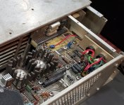
There's no really good way to put an ammeter in series between the power supply and the backplane. I'd have to find the weird pitch 26-position card edge connector, build an extension with gaps in it, and put your ammeter across that. That, or I'd have to destructively damage traces and that's a non-starter for me. You can see where the PSU sockets into what we call the "resistor board" which then sockets into the backplane PCB itself.
D2 1N3899... to clarify, do you mean CR2 on the schematic? If so, my diode checker function reads no reverse voltage pass through, and 0.34V forward voltage on both CR2 and CR1 (the latter is the equivalent for the 15V regulator).Looking at the schematic, the 723 (I prefer LM723C because it's a later revision) is in a switching PSU configuration. Have you replaced D2 (1N3899R)? That functions as a snubber and can lead to all sorts of woe if it's failing. Note the "R" on the part--it's a stud-mounted diode, but in reverse polarity from a standard 1N3899.
Just a guess...
The first problem I solved after reforming/replacing the 5 big capacitors was figuring out why the main fuse would blow instantly on power-up. The big bridge rectifier was the reason -- one of the internal diodes had shorted closed.R27 shouldn't be getting anywhere near that hot, it should only be disappating about 1/2 of its rated power. I would have guessed a bad diode in the bridge rectifier but you've already replaced that.
I really do not want to have to shotgun replace the remaining big capacitors, wire wound resistors, diodes, and transistors for this supply to be considered "good" again. The big caps alone will be quite expensive to replace. Besides, the replacements have arrived.
Have you considered possibly using a Hall-effect current probe such as this https://www.crowdsupply.com/weston-braun/little-bee to measure current without ripping up traces?
Chuck(G)
25k Member
Yes, CR2--and you've verified that it's the "R" variant on the board (could be that someone tried a standard '3899 there. That would not be good.)
pbirkel@gmail.com
Veteran Member
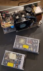
Which supplies are those two? My problem is no PSU at all; just a cavity presents itself to my gaze .... My preliminary estimates on the bin-packing problem weren't coming up with an elegant solution that also accommodated airflow, so I'm now quite interested in your approach going forward ... hoping to apply the same solution here.Besides, the replacements have arrived.
View attachment 1240989
In case you haven't already seen it there's useful information/experience in
He was fortunate to have a *lot* of space to work with. You (and I) don't ...
CommodoreZ
Experienced Member
Indeed, I am familiar with Forgotten Machines' work. He's one of the resources I've been consulting in this process.Which supplies are those two? My problem is no PSU at all; just a cavity presents itself to my gaze .... My preliminary estimates on the bin-packing problem weren't coming up with an elegant solution that also accommodated airflow, so I'm now quite interested in your approach going forward ... hoping to apply the same solution here.
He was fortunate to have a *lot* of space to work with. You (and I) don't ...
The switching supplies I've selected are a pair of Meanwells: RT-125A and LRS-150-15. The former will provide the 5V, -5V, and 12V for the 11-17V lamp voltage, as well as running case fans. The latter provides 15V which will power the core memory. I don't use -15V on my system, so I was able to omit that. For now, I would recommend against buying what I've selected until we can confirm they'll be suitable for the job, but I am happy to share my results -- especially if it helps revive another Nova!
May I ask what model of Nova you have?
Confirmed, it is the 1N3899R variant of the diode.Yes, CR2--and you've verified that it's the "R" variant on the board (could be that someone tried a standard '3899 there. That would not be good.)
I was not aware that current probes existed. The difficult part is finding a good place to measure, as the 5V and 15V rails on the power supply PCB are double sided -- top and bottom. Can you get an accurate measurement while only sampling one side?Have you considered possibly using a Hall-effect current probe such as this https://www.crowdsupply.com/weston-braun/little-bee to measure current without ripping up traces?
pbirkel@gmail.com
Veteran Member
May I ask what model of Nova you have?
It's a 1200 chassis minus PSU. Boards came from other sources over several years, however the key ones are a "NOVA 1200 CPU", a pair of "NOVA 4K MEMORY", a "NOVA 8K MEMORY", a pair of "DGC NOVA CASSETTE I/O" (both TTY-only), and a "DGC NOVA CASSETTE I/O 2" (almost fully populated; W13 strapped "4800 - 712").
thunter0512
Veteran Member
I don't like these type of shotgun style parts replacements. They are a lot of work and expense and rarely solve anything. It may be better to carefully analyze the circuit and understand how it works. An LM723 based regulator is not too complicated although in this example DG engineers did a few odd things which I don't fully understand. With the limited understanding I would suggest the following simple tests with a load which takes about 1A (suitable light bulb or resistor):I have replaced a significant portion of the components already. Here's a recap of everything I've done on this power supply so far:
...
View attachment 1240965
- Lift one leg each of R23 and C15 and see if 5V becomes stable. These two components do something obscure to the non-inverting input of the LM723 and are not necessary for bare-bones regulation but may do some nice-to-have filtering I don't quite understand. The circuit will work without them. I suspect C15 may be faulty and do something funky. If this did not resolve the problem then (and only then) go to the next step.
- Lift one leg of C13 which is another nice-to-have for current-limit smoothing, but may be faulty and is not necessary for bare-bones regulation. The circuit will work without it. There is a chance that C13 is leaky. If this did not resolve the problem then (and only then) go to the next step.
- Lift one leg of CR5 which seems to protect the current limit input but again is not essential for regulation to work.
Please let me know if these steps fixed your 5V stability issue.
Tom Hunter
I'm assuming you are saying that the 5 and 15 traces don't overlap each other on the opposite sides of the board, but that each one is duplicated on the opposite sides of the board, for some distance, and they share the total load for that rail. Obviously if you only have one trace it carries the entire current and you could calibrate for an absolute reading with the probe. More often you would probably not calibrate for absolute and just use it to find relative ratios between probed different locations to find where the heavy load was.I was not aware that current probes existed. The difficult part is finding a good place to measure, as the 5V and 15V rails on the power supply PCB are double sided -- top and bottom. Can you get an accurate measurement while only sampling one side?
Another alternative would be to use a thermal camera and see what is getting hot.
firebirdta84
Experienced Member
Ah, thanks for linking my resources here! By a *lot* of space, you mean that I'm working with a 17-slot chassis with a double-high power supply bay, and the single-power supply bay allows for only 1/2 the room? So true. But so far, this solution has worked very well. It's all in how much you trust your own skills, and the reliability of the modern power supplies you're using. As you can see by the videos, I do get *edgy* a bit...He was fortunate to have a *lot* of space to work with. You (and I) don't ...
And, here's a ULR directly to the page I created for this power supply build. https://entrex480.blogspot.com/2019/09/building-power-supply-for-dg-nova-dss.html The URL listed above seems to not quite get us there, formatting issues I don't quite get.
Anyway, hope this helps, and the DG Nova / DCC D-116 power supply adventures continue!
CommodoreZ
Experienced Member
Yes, they do overlap on the board. On the connector to the resistor board, they're sandwiched top and bottom.I'm assuming you are saying that the 5 and 15 traces don't overlap each other on the opposite sides of the board, but that each one is duplicated on the opposite sides of the board, for some distance, and they share the total load for that rail. Obviously if you only have one trace it carries the entire current and you could calibrate for an absolute reading with the probe. More often you would probably not calibrate for absolute and just use it to find relative ratios between probed different locations to find where the heavy load was.
Another alternative would be to use a thermal camera and see what is getting hot.
As for heat output with a thermal camera, here's two photos from a series I took a few months back when I was studying replacing the fan. Eventually, I elected not to.
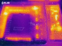
This is how I knew that the 600ohm resistor was getting above 300F. I don't know just how hot because that's as high as the FLIR will measure.
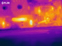
Here's one from last night. There is some offset between the thermal camera and the human-range camera, as well as some light reflecting from my bench lamps, but things get hot fast.
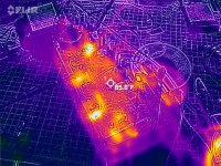
During my most recent tests, I was noticing that the switchmode whine was... irregular. Concerningly irregular. I also noticed a burning smell after only 90 seconds of operation, which made me uncomfortable enough to shut it off and not want to test the switchmode section any further.
I mentioned it before, but I'm not a fan of shotgun replacements either. Everything I replaced before I did so with a reason. It was either known failed, or suspected of drifting out of spec, and hard to test in-situ under load, so it was safer to swap.I don't like these type of shotgun style parts replacements. They are a lot of work and expense and rarely solve anything. It may be better to carefully analyze the circuit and understand how it works. An LM723 based regulator is not too complicated although in this example DG engineers did a few odd things which I don't fully understand. With the limited understanding I would suggest the following simple tests with a load which takes about 1A (suitable light bulb or resistor):
An LM723 based regulator is easy to understand if it's being used for linear regulation applications, but these two are being leveraged as switchmode, which isn't exactly common. DG did it in a janky way, and I don't like the risk it puts on the computer part of the Nova.
I've done my fair share of load tests using indicator bulbs, checking ripple with my scope at various points in my test process, and it's just a weird design. The large capacitor across the 5V rail to smooth it is one of the few that's new, so why does it ripple that much? Who knows.
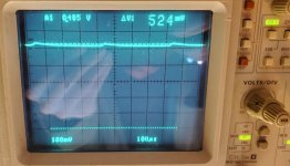
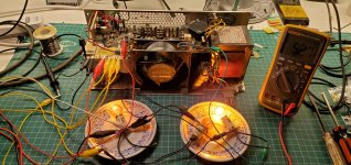
Here's from the most recent tests (after I powered down), where the PSU whine was outside of the expected pitch and range that I have come to expect either under test or operation in the machine, coupled with that burning smell. Probes go up to the scope, and dummy load bulbs are wired in to keep the switchmode section happy.
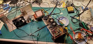
The point is that I just don't trust this power supply any further than I can throw it (which isn't far because it weighs a ton). It's just not worth fixing at this point. I've been talking with firebirdta84 and Nevets01 (who has a DCC-116, a Nova 1200 clone) about replicating the edge connector so modern switchmode modules can be installed and we're starting to devise a gameplan. I'll keep y'all posted on how that progresses.
Last edited:
thunter0512
Veteran Member
I have never seen an LM723 used in this way so I struggled to understand some of the detail. I have since searched for "LM723 switch mode" and found an interesting article about it:
 hackaday.com

The UA723 As A Switch Mode Regulator
If you are an electronic engineer or received an education in electronics that went beyond the very basics, there is a good chance that you will be familiar with the Fairchild μA723. This chip desi…
jlang
Veteran Member
Your load on the 5 volt power supply is too little. The regulator is "going linear" and the dissipation in the pass transistor skyrockets.
This circuit is not weird or uncommon. It's an example from the TI data sheet.
I'll try to explain it.
It's a positive regulator with an external PNP pass transistor. The output wiring looks odd because the external pass transistor inverts so
it's driven from the collector of the internal pass transistor not from the output pin.
Now let's turn it into a switcher.... add inductor, large output cap and flyback diode. sense connected to the cap.
It still acts like a linear regulator. Now to make it switch. We add positive feedback from the pass transistor collector to the reference input.
let's turn it on!
Sense is lower than reference so output turns on. output voltage rises eventually sense reaches reference, 723 starts reducing output
because sense is higher than reference. Pass transistor collector starts dropping and reference also drops (due to feedback) reenforcing the turn off.
Energy in the output circuit (cap inductor diode) will drop. When sense drops below reference the 723 turns on the pass transistor and another
charge/discharge cycle begins
The 723 will switch between sense too high and sense too low. It can't reach sense just right because of the feedback.
The average will be sense just right.
The output ripple is equal to the value of the positive feedback. The size of the output cap will not change the amplitude of the ripple.
But it will change the frequency. The inductor must be large enough to not saturate.
After all this I agree with you. If you can't get to the point that you trust this supply then use something else.
But don't toss it. Save it. Pass it on.
joe
jlang
Veteran Member
The DEC H744 uses a 723 as a switch mode regulator. This was common in the 70's.I have never seen an LM723 used in this way so I struggled to understand some of the detail. I have since searched for "LM723 switch mode" and found an interesting article about it:

The UA723 As A Switch Mode Regulator
If you are an electronic engineer or received an education in electronics that went beyond the very basics, there is a good chance that you will be familiar with the Fairchild μA723. This chip desi…hackaday.com
Chuck(G)
25k Member
Indeed. The DG circuit is pretty much straight out of the application notes. This was not uncommon before high-frequency primary circuits became the norm (early ones relied on the availability of TV horizontal output transistors).The DEC H744 uses a 723 as a switch mode regulator. This was common in the 70's.
firebirdta84
Experienced Member
Thanks everyone for the fantastic info and perspectives on this thread. It's getting quite interesting!
For anyone interested, I believe I have at least 5 Data General Nova PSUs identical to Commodore Z's. All of them have problems, as expected with hardware like this aged 50+ years.
I also have at least 3 DCC D-116 PSUs. Also with similar problems, even though their design is radically different.
Most of these PSUs were stored in moist and humid environments over the decades, so corrosion has proliferated.
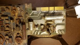
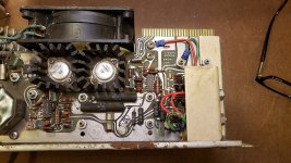
I've decided that, if/when I ever tackle repair and testing of these PSUs, it will be after I have a number of DG Nova and DCC D-116 systems up and running on my "Modern PSU Replacement' modules.
When I'm ready, maybe someday I'll do a "magic smoke release" festival video on my YouTube channel, featuring the problems on each of these PSUs in rapid succession. By then, I think I'll be comfortable enough to take on an "assembly line" of repairs on these.
Besides, for me, I always find it's more fun to repair items like this in bulk, swapping parts and testing, instead of one-by-one in isolation, without other units to test and pull parts from.
Again, love the discussion here! Thanks, everyone.
For anyone interested, I believe I have at least 5 Data General Nova PSUs identical to Commodore Z's. All of them have problems, as expected with hardware like this aged 50+ years.
I also have at least 3 DCC D-116 PSUs. Also with similar problems, even though their design is radically different.
Most of these PSUs were stored in moist and humid environments over the decades, so corrosion has proliferated.


I've decided that, if/when I ever tackle repair and testing of these PSUs, it will be after I have a number of DG Nova and DCC D-116 systems up and running on my "Modern PSU Replacement' modules.
When I'm ready, maybe someday I'll do a "magic smoke release" festival video on my YouTube channel, featuring the problems on each of these PSUs in rapid succession. By then, I think I'll be comfortable enough to take on an "assembly line" of repairs on these.
Besides, for me, I always find it's more fun to repair items like this in bulk, swapping parts and testing, instead of one-by-one in isolation, without other units to test and pull parts from.
Again, love the discussion here! Thanks, everyone.
Last edited:
Nevets01
Experienced Member
I'm with Z and firebird on this.
My D-116 PSU has caused me much grief (including earning me the dubious honor of 'first to smoke' at VCFMW), and at this point, I think my best option for getting the computer going again will be to put the original power supply on a shelf (and KEEP it there) and start over with modern components.
My D-116 PSU has caused me much grief (including earning me the dubious honor of 'first to smoke' at VCFMW), and at this point, I think my best option for getting the computer going again will be to put the original power supply on a shelf (and KEEP it there) and start over with modern components.
Marty
Veteran Member
Hi;
Years ago I had both a Nova and a Nova 1200.. The power Supply was bad in my 1200, I never was able to make it work..
So, I gave what I had to Bruce Ray, I think He still has both of them.. Bruce is a Great Guy.. I have known Him for many many years..
The Nova (plain) had a better Power Supply than the 1200 did.. The Nova plain needed work as well, I don't remember what it was..
Thank You Marty
