Qbus
Veteran Member
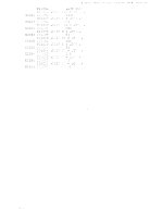
Mysterious additional pages, never made any sense to me.
| VCF West | Aug 01 - 02 2025, | CHM, Mountain View, CA |
| VCF Midwest | Sep 13 - 14 2025, | Schaumburg, IL |
| VCF Montreal | Jan 24 - 25, 2026, | RMC Saint Jean, Montreal, Canada |
| VCF SoCal | Feb 14 - 15, 2026, | Hotel Fera, Orange CA |
| VCF Southwest | May 29 - 31, 2026, | Westin Dallas Fort Worth Airport |
| VCF Southeast | June, 2026 | Atlanta, GA |
Excellent. I've been compiling a list of programs, resources, and various links to the Nova community at large here: https://www.commodorez.com/novarsc.htmlOriginal document including instructions and source:

Thank you Qbus for discovering and publicizing this debugger in the first place.Thank you Qbus. Original document including instructions and source:


Nice collection!So by the time I found out about this, a lot of the stuff had been parted out and some of it scrapped. Apparently the original owners had been trying to work with several hobbyists and amateur radio operators for like, two years or something, and had gotten a lot of "definitely interested, will be by to pay and pick up" type of replies that resulted in no action, and had gotten tired of it.
Most of the DG and Computer Automation stuff was connected to typesetting machines, there were two Kurzweil OCR systems but they were the later integrated packages, not the big early boxes with a full-fledged Nova attached. The Kurzweil stuff may have an OEMed Nova or Nova-compatible board in it, too. I believe they'd told me the Fairchild 2300 (TRW 130, AN/UYK-1...originally a 1950s nuclear sub satellite nav computer) was also hooked up to a typesetter.
We ended up making a second trip up to pick up some other large things that weren't really shippable -- the remains of at least a dozen Kaypros, the guts out of two Linotron 202s that had gotten scrapped, misc. cables and other bits that had been found since the original pick-up, and a box of board scrap that had come from some of the equipment.
I suspect CommodoreZ's Nova 1200 was indeed connected to that Teletype at one point, though the Teletype may have shared service between several computers, such as the Fairchild 2300, which also has current loop output. Don't know what the Nova 1200 in particular was doing, though.
Here's some pictures of the stuff, unloaded in the new building (not everything is from the same lot, in the second picture):
It pretty well filled the back of the 24-foot Mack box truck:
There was a bunch of Sun stuff too, which was one of the big reasons I was interested in the stuff (still support it for my day-job). TangentDelta has been working on a lot of the Computer Automation Naked Mini stuff.
Have you pursued the OCR conversion?Thank you Qbus for discovering and publicizing this debugger in the first place.
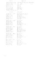
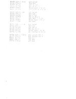
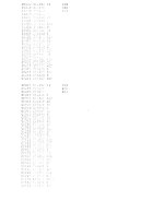
Thank you Paul for pointing us to the nice and readable manual with program listing. It may even be convertible to text via OCR.
I am not a fan of toggling in more than say twenty 16 bit values because I am guaranteed to make mistakes.
I have upgraded my Nova 2 with the "Program Load" feature, so I prefer to type in the source code from a listing once and then assemble once and load with the Binary Loader forever, rather than toggle in 16 bit octal values over and over. But maybe that is just me being weird.
Tom
I did, but the OCR conversion quality was very poor. I used ABBYY FineReader 14 for the conversion attempt.Have you pursued the OCR conversion?
007300 .LOC 7300
07300014555 A: DSZ BPSWT ;START HERE
07301 040406 STA 0,ACS JSAVE ACS
O/^oo 004466 STA 1 ,ACS+1
O73C3 050466 STA 2,ACS+2
07304 054466 STA 3,ACS+3
07305 020470 LDA 0# INST J5ETOP FREAK INSTRUCTION
07306 040470 STA 0,PIN5I
07307 020465 LDA O,BADDR 1SET PROOFED ADDRESS DO
07310 C40550 STA O,PADDR .BREAK FAY BE CHANGED.
7311 158660 5UBCR 2,2 .SAVE CARRY
07312 fr?577 SKPEZ CPU JftBYEYBER STATE OF
07313 151400 INC 2,2 ‘INTERRUPT FLOP.
07314 060277 C77l NIOC CPU .TURN OF INTERRUPT-
07315 050456 STA 2,AC5+4 JCARRY SAVE
7316 06351 1 SKPBZ TTO IRF.MBER THE STATE OF
07317 000777 JHR .-1 JTTO DONE FLAG.
07380 063711 SKPDZ TTO
07381 158000 ADC 2,2
07322 050540 STA 2,TFLAG
07323 024451 LDA 1,BADDR MP ENTERED VIA
07324 010531 1ST BFSWT JBREAK POINT TYPE THE
07325004502 AAAI JSR POCT JBREAK POINT ADDRESS.
07386 020537 LDA 0,C15
07327 004521 JSR TYPE IECHO CARRIAGE RETURN.
07330 020534 AAl LDA 0,02 JTYPE LINE FEED
O7J31 004517 JSR TYPE
07332 040531 STA O,OPEN .REGISTER OPEN/CLOSE
07333 152400 SUB 2,2
07334 050521 STA 2,BPSWT .BREAK POINT SWITCH.
07335 050524 STA 2,DIN JDATA TYPED SWITCH
07336 063610 SKPDN TTI
07337 000777 JYP .-I
07340 060610 DI AC O,TTI MNPU! A CHAR
07341 00450? BBs JSR TYPE J ECHO
07342 034575 LDA 3,0 77
07343 163^00 AND 3,0 INASKPARITY
07344 034513 LDA 3>C7O ICHECR FOR A DIGIT
07345 116032 ADCZ# 0,3,SZC
07346 034525 LDA 3,CF60
07347 117046 ADDO 0,3, SEP
07350 004410 JSR SERH INOT ADIGIT 0-7
07351 010510 CCl 1ST DIN ’ DIGIT SWITCH
07352 15H20 KOVEL 2,2 JASSE^BLE DIGITS
07353 153120 AODZL 2,2
07354 173003 ADD 3,2,SNC ISKIP IF EXTRA DIGIT.
07355 000761 JW BB-3
07356 02073*6 GOOFi LDA 0,C77 I OPERATOR ERROR.
0735? 000750 JMP Aft*1


/INTR line for the serial interface on the Cassette I/O board to signal to the CPU. Seems like it's stuck triggering all the time and should not be, which is no bueno.
/MSKO signal wasn't being generated properly on the CPU board. The chip in question is not a flavor of 7402. but rather a Signetics N8885A which is not pin compatible. The first input pin and the output pin are switched for each gate, and I don't keep many spare Signetics parts on hand.

/DATOB signal isn't being generated, so I can't even see it the effects of /MSKO possibly being fixed.
/INTR jumped around a few times, though I'm convinced that might have been from me getting mixed up on gates as I was working. The Clock Interrupt was the one in particular that wouldn't go away. Note the cyan and magenta signals coming out of U117 CLK DONE. They should be mirrored perfectly and they aren't. I also noted that pin 3 never changed, and yet, even with that /CLK BUSY signal at a 1 all the time, CLK DONE was always set. You would think that the /RESET pulse (yellow trace, pin 4) would clear it and keep it cleared, but it kept setting again at the conclusion of that pulse.

/PRESET lines), I added in a pull-up resistor. Original 7474's don't need those, hence why DG doesn't have one.


Y. Gave it a BASIC program and... it runs! IT RUNS!
Although pullups are always a good idea and required for with CMOS inputs, I don't think they are necessary with 74LS logic.Since there is no pull-up or driving logic on pin 1 (one of the/PRESETlines), I added in a pull-up resistor. Original 7474's don't need those, hence why DG doesn't have one.

")

Nova 1200 Logic Test diagnostic tape. Great.