Upcoming Events:
| VCF West | Aug 01 - 02 2025, | CHM, Mountain View, CA |
| VCF Midwest | Sep 13 - 14 2025, | Schaumburg, IL |
| VCF Montreal | Jan 24 - 25, 2026, | RMC Saint Jean, Montreal, Canada |
| VCF SoCal | Feb 14 - 15, 2026, | Hotel Fera, Orange CA |
| VCF Southwest | May 29 - 31, 2026, | Westin Dallas Fort Worth Airport |
| VCF Southeast | June, 2026 | Atlanta, GA |
-
Please review our updated Terms and Rules here
You are using an out of date browser. It may not display this or other websites correctly.
You should upgrade or use an alternative browser.
You should upgrade or use an alternative browser.
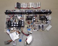
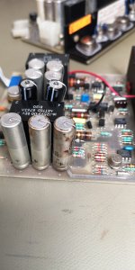
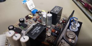
DEC H780 Supply Caps
- Thread starter glitch
- Start date
NF6X
Veteran Member
I think I can smell them through the Internet.
pbirkel@gmail.com
Veteran Member
What prompted you to pull them in the first place? Just pull-and-replace "on general principles"?
DDS
Veteran Member
Eww!
Just, eww!
Just, eww!
glitch
Veteran Member
What prompted you to pull them in the first place? Just pull-and-replace "on general principles"?
Yeah, I don't bother powering anything up without going through the PSU anymore. Not worth blowing something up for a few hours and $10 in parts.
MattisLind
Veteran Member
Just curious, how do you rack mount your BA11-M? I have one and haven’t figured out if it just is fastened through screws in the front or if it need some kind of support brackets in the rear of the box.
glitch
Veteran Member
Ok. I haven't had these go bad, and these days I back feed +5 and +12 from a current limited supply to see if anything is shorted/get the caps in line before powering everything up. Makes life a lot easier.
Huh, really? I've had these long, thin, epoxy-sealed oldschool low ESR caps fail in all sorts of equipment. To be clear, I have never applied power to the RKV11-D since I've owned it (2014), so this happened either before I got it, or sitting on a shelf.
Usually I'm disassembling a supply to clean it anyway, and if it's open I might as well recap since we stock most of the parts (though I would even if we didn't).
I'd be hesitant to backfeed a supply, especially a switcher, but if it's current-limited I guess the amount of possible damage is lowish.
glitch
Veteran Member
Just curious, how do you rack mount your BA11-M? I have one and haven’t figured out if it just is fastened through screws in the front or if it need some kind of support brackets in the rear of the box.
I have one front-mounted above the PDP-11/10 at the moment (storage position) but it's not great. The drawings say there's supposed to be back-end support brackets. Neither my RKV11-D nor my regular QBus BA11-M have the support brackets. If someone has originals to measure/copy, I'd be interested in running some new ones; otherwise, I might see about drawing them up myself.
jlang
Veteran Member
I've had to make several pairs of rear mounting brackets. I have an original set but it doesn't match the rack I have.I have one front-mounted above the PDP-11/10 at the moment (storage position) but it's not great. The drawings say there's supposed to be back-end support brackets. Neither my RKV11-D nor my regular QBus BA11-M have the support brackets. If someone has originals to measure/copy, I'd be interested in running some new ones; otherwise, I might see about drawing them up myself.
It's a simple right angle bracket that bolts to the rear vertical rail and bolts to the rack slide.
Make your own. I've seen what you can do.
glitch
Veteran Member
Make your own. I've seen what you can do.
Oh, sure, I could knock out one set on the sheet metal brake...but we also use a localish sheet metal shop that does good work at great prices and could make 25 pairs
Adriaan
Experienced Member
Can you explain for me what “back feed” means?Ok. I haven't had these go bad, and these days I back feed +5 and +12 from a current limited supply to see if anything is shorted/get the caps in line before powering everything up. Makes life a lot easier.
I’m new in old gear
MattisLind
Veteran Member
If you decide to have them made I could use one pair. Only have one BA11-M box. But perhaps I can do one pair myself if it is just a 90 degree bend.Oh, sure, I could knock out one set on the sheet metal brake...but we also use a localish sheet metal shop that does good work at great prices and could make 25 pairsI just don't know if other people need it.
It has to be quite long brackets since the BA11-M is so short. I was looking around for drawings for how it was supposed to be mounted in the cabinet but didn't find any. Could you share a link?
BTW. Do you have a picture of the small detail in the front that you screw the bezel into? Mine seem to be missing. Need to figure out how to manufacture those as well..
I usually backfeed switchers to test the crowbar and regulation circuitry. Current limited supply of course and without any input voltage on the PSU (except for the control circuitry). You have rectifiers directly of the transformer so not much current can flow in that direction anyhow. Usually just the filter and a crowbar there.
glitch
Veteran Member
If you decide to have them made I could use one pair. Only have one BA11-M box. But perhaps I can do one pair myself if it is just a 90 degree bend.
It has to be quite long brackets since the BA11-M is so short. I was looking around for drawings for how it was supposed to be mounted in the cabinet but didn't find any. Could you share a link?
It's in the old PDP-11/03 printset:
The bracket is just noted as a customer-installed part and is not dimensioned, which is why I don't know exactly what size it's supposed to be
BTW. Do you have a picture of the small detail in the front that you screw the bezel into? Mine seem to be missing. Need to figure out how to manufacture those as well..
I can get a picture on the RKV11-D but IIRC my QBus BA11-M is missing it also. It looks like the RKV11-D may be different, but I'm not sure as neither of mine have covers!
I usually backfeed switchers to test the crowbar and regulation circuitry. Current limited supply of course and without any input voltage on the PSU (except for the control circuitry). You have rectifiers directly of the transformer so not much current can flow in that direction anyhow. Usually just the filter and a crowbar there.
I guess...but won't you be driving current sense elements backwards? With current limiting it probably prevents anything catastrophic from happening. And it still doesn't help with the DC bulk cap, so you're still either opening the supply to reform out-of-circuit, or bringing it up on a variac (not always a good idea on some switcher topologies).
I test with dummy loads and don't usually try and trip the crowbar.
daver2
10k Member
>>> Can you explain for me what “back feed” means?
It means to connect a power supply 'backwards'.
What I mean by this is you keep the input to the power supply disconnected and feed the output(s) from a current-limited supply of a lower voltage than the power supply outputs, and then slowly ramp up the voltage to the specified power supply output voltage for the rail.
The large smoothing capacitors are usually on the output side of a power supply, so by feeding the power supply this way you can usually test and reform the electrolytic capacitors without removing them.
Like everything, this may only work under certain circumstances. We use a lot of power supplies where they have output diodes (blocking diodes) so we can parallel them up (for redundancy purposes). In this case, this scenario would not work (the blocking diodes will be preventing the requisite current flow). However, if you already know this, you can put a red shorting link across the blocking diode and it will work. The wire colour is not important of course (!) it just stands out so you remember to remove it before using the power supply...
Having the schematic diagram for the piece of equipment to hand, and looking at the options available to you, can prevent a lot of disassembly work when testing and reforming power supplies.
Does this make sense?
Dave
Last edited:
pbirkel@gmail.com
Veteran Member
I especially like the "Typ both sides" comment in Note #1 (page 4 of 174) as well as a comment on Note #3. The SMPS side would probably be sufficient as a practical matter, however best to be safe :-}. Recessed flat-head machine bolts are critical as there's essentially zero clearance when extracting the backplane assembly or SMPS. I used flat aluminum sheet and bolted to the inner side-facing mounting points on the rear posts rather than extending all the way to the back and using a right-angle to reach the rear-facing mounting points.It's in the old PDP-11/03 printset:
The bracket is just noted as a customer-installed part and is not dimensioned, which is why I don't know exactly what size it's supposed to be
pbirkel@gmail.com
Veteran Member
Diverging form the main topic, but ... I've heard of the use of blocking diodes to run SMPS in parallel but not seen much specific on this configuration. How do you keep the voltage-drop down across the blocking diodes? Does this configuration assume that there is remote voltage sensing on all linked SMPS so that they automatically compensate for the drop? Under normal conditions will the linked SMPS split the load more-or-less equally?Like everything, this may only work under certain circumstances. We use a lot of power supplies where they have output diodes (blocking diodes) so we can parallel them up (for redundancy purposes). In this case, this scenario would not work (the blocking diodes will be preventing the requisite current flow). However, if you already know this, you can put a red shorting link across the blocking diode and it will work. The wire colour is not important of course (!) it just stands out so you remember to remove it before using the power supply...
daver2
10k Member
Yes, remote sensing feedback. Usually taken from the power supply bus-bars.
Actually, we are just replacing our SMPS units with modern ones, and we have gone for a design where one runs with the full load and the other with no load. This just seems 'wrong' to me - but the SMPS units are designed for operation like this.
Most of the power supplies we use blocking diodes on are linear of course.
Dave
pbirkel@gmail.com
Veteran Member
So there's some sort of side-band signalling between them then?Actually, we are just replacing our SMPS units with modern ones, and we have gone for a design where one runs with the full load and the other with no load. This just seems 'wrong' to me - but the SMPS units are designed for operation like this.
Which sort do you use to keep the drop down then?Most of the power supplies we use blocking diodes on are linear ...
Why "of course"?... are linear of course.
Roland Huisman
Veteran Member
I had the same with my low profile PDP11/34 and its H777 power supply. I never switch on these things before checking the mains circuit and power electronics. I ended up replacing all 14 electrolytic capacitors. But it was rewarding to have a working PDP11/34 


