• Please review our updated Terms and Rules here

Diagnose issues: PET 4032 with PETTEST ROM

If you suspect a digital issue, a very handy tool for quick diagnosis and tracing is a simple logic probe. You give it power and ground and you can poke it into the circuit on IC legs and such and check if the signal is high, low, floating (nothing driving it), or fluctuating (either rapidly or pulses). They're honestly much faster to work with than an oscilloscope for certain tasks, albeit more limited, and much much cheaper. Unlike a logic analyzer there's only one channel but they're much more responsive for quick checking if signals make sense in a digital circuit.

I don't even bother with one. The data provided is severely limited. I would agree that "if it is all you have" though use it.

When I was a boy around 8 years old I could repair most transistor radios. All I had was a crystal earpiece that I could connect onto points in the audio circuit to hear the sound. Then I used the earpiece with a germanium diode and I could demodulate the audio off an RF carrier.

One day I got an analog multi-meter and I could test voltages, specifically ones across the emitter resistors of the transistor stages. That way I could determine the emitter currents of the transistors and check their DC bias conditions. I thought " I had it made" when I was about 15 years old.

Then one day as I hit about 20 years old, a friend loaned me a scope. All of a sudden I had a view into a previously concealed world of voltages changing with time. After that there was no going back.

Since then I have equiped myslf with good scopes like the Tek 2465B and I can see into circuits operating at over 400MHz.

A logic probe, by comparison, is a hopeless entity and a mere "toy". Better than nothing though, but it is nothing at all like a good scope for fault finding analog or digital circuitry.

Logic probes are useful to tell if a level is constantly low, high or has pulses.

Oddly in the area of Dynamo and Alternator voltage regulators, the power supply to the field winding (in the Dynamo case) and the Stator (in the alternator case) can at times have these three conditions.

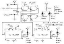
A while back I designed a logic probe, which was very similar in its operating principles to a logic probe for Cmos or TTL circuitry, that could be used as a fault finding tool for Auto Electricians working with dynamo and alternator voltage regulators:

 
Last edited:
With the caveat that their frequency response is severely limited (when compared to a reasonable oscilloscope)

The logic probes they’re selling for $12 on eBay claim to be good up to 20mhz, that’s at least as good as my antique oscilloscope and should be good enough for most PET related poking, I’d think?

I have an old Archer-brand probe in my toolbox and I’ve actually been surprised at how handy it is to give something a quick poke to see if it’s alive or not. (and “alive or not” is often enough for round one) Hasn’t lead me wrong yet that I can remember; now I’m wondering if the box has the response specs printed on it…
If logic pulses are in the sub 100nS range and infrequently occurring sometimes a logic probe is useful to see if they are there, as they get effectively stretched to run the LED, because they can be difficult to display on an analog scope. But of course knowing a pulse is present, doesn't tell you about the character of the pulse and many faults are shown up by the form of a signal over time.

The ideal logic probe to use has an input with the same family of logic devices you are testing and is therefore compatible with the input voltage threshold, max rise & fall times and upper frequency response of the devices. But, in a attempt to make cheap logic probes that do both Cmos and and TTL, the designs of some are sub-optimal and you would be better to make one yourself as a home project, than be led up the garden path by a poorly performing cheap ebay probe. I think we saw a case of this recently where Desperado's logic probe was blind to a 1MHz signal, making a logic IC look defective when it was not. If you check on the net images, you will see there are a plethora of designs for simple logic probes, that display high, low, pulses etc and some are much better than others in reporting valid signals of the IC family they are supposed to be testing.

The attached circuit is a good design, because it interfaces to TTL correctly and it has independent pulse stretchers (monostables) for high and low going narrow pulses.

After a while though, it becomes obvious using the scope, that narrow pulses are there (even if difficult to see on screen) because the time-base is reliably triggered and good scopes have trigger level settings with on screen displays for the level. So in effect you can also measure the amplitude of the very narrow pulses by finding out the level that just triggers the scope. If the scope has a delay time-base, most of these narrow pulses can also be fairly easily seen, that is if they are repetitive enough above a few 10's of Hz. Below that its better to have a scope with storage functions.
 

Attachments

  • probe.jpg
    probe.jpg
    73.8 KB · Views: 6
Last edited:
>>> claim to be good up to 20 MHz.

And they lay golden eggs :)...

Hey, I'm not arguing that these things are in any way a replacement for an oscilloscope, but my oscilloscope weighs 20 pounds and I have a tiny workbench, so a simple little dingus that can be strapped on in 30 seconds to take a pulse feels like it has a legit place in any toolbox. Yes, sometimes the patient needs to go in the MRI machine to see the problem, but not *every* time.

Pulled it out and looked at it, I guess I slagged my logic probe by calling it an Archer, it's a CircuitMate LP25. (Its little cardboard box just looks like it came from a late 1970's Radio Shack.) And according to the box it's good up to 25mhz and can detect pulses down to 30ns, and has some kind of tracking memory to help it trigger correctly on intermittent pulses. It's also super handy that it has a beeper so I don't even need to divert my eyes to look at a screen or LED; all I need to do is listen for the chirping. FWIW, I've used it to find real problems on machines running at 7.16mhz.

(For instance, a forehead-slapper of a mistake where I didn't properly qualify writes to a 74LS670 memory mapper I built, causing random memory writes that happened to contain similar bits in their addresses to clobber the register contents. One poke with the logic probe while the machine was running some busywork revealed the irregular chirping that shouldn't have been there, boom, problem confirmed.)

Maybe the cheap eBay ones are garbage, but my old one works very well for what it's designed to do.
 
Maybe the cheap eBay ones are garbage, but my old one works very well for what it's designed to do.
This is what has happened because it it easier to use a single pic microcontroller than an array of vintage TTL logic IC's. Most standard vintage TTL's are good to 20MHz at least, some make it to 30MHz. Obviously S & F variants are faster. This is why your vintage logic probe from the 1970's era is so good and meets its specs.

If the design of the logic probe I posted (which was just lifted from the net ) was made with 74F TTL's it would be pretty darn good and probably be able to detect pulses even narrower than 30nS.
 
I generally recommend the small Hitachi analog scopes as starters, V209 or V509 because they are super compact and don't occupy much bench space at all. The 509 has a delay time-base and is 50Mhz, the 209 is 20 MHz, both would work to help fault find a PET. The 209 is often cheaper and plentiful and at least close to $100 and infinitely better than any new digital scope at that price area. One feature is they have a very high final anode voltage for the small sized CRT at 10kv and they have a super bright trace.

The trick is, never buy one that is cosmetically beaten up, missing its carry handle. If you can find a good looking one cosmetically & working, invariably it will have been looked after. The V209 appears on ebay frequently:

I was able to buy a Hitachi 209 off of ebay, but it didn't come with any probes. Any recommendation for probes?
 
This question was answered in a fairly recent thread by myself.

I am on my phone at the moment, so it is not too easy to look it up...

Dave
 
I'm back! I found a great deal on a Hitatchi V-209 . I ran through some tutorial videos today.

pet.jpeg

UA19 is responsible for data bit 0 (D0) of the lower bank of 16K DRAM. So this would be the chip to try. However, I am thinking that the data bit is stuck at '0' - and this (generally) is not good for a piggy-back test to work. Stuck at '1' is usually much better.

What is the procedure here for testing the DRAM chips, trying to find the bad one(s)?
 
I'm back! I found a great deal on a Hitatchi V-209 . I ran through some tutorial videos today.


What is the procedure here for testing the DRAM chips, trying to find the bad one(s)?

Hi irataxy

I'm far from qualified in repairs but I've had a quick squiz over your post and it looks like a bad ram or possible address line could be an issue? I think one way of ruling out an address line is to use the romulator as a NOP and check each address line with your scope. Each address line should halve (or is it double?) it's frequency as you go down the address line. I don't mean to give you steps on what to look for, but ideas to search for on these forums to help you progress forward.

Cheers
 
Fire my PETTESTER up and post a photograph of the fault screen that is displayed. We then look at the display and look for patterns that will identify the initial faulty chip(s). We replace those and try again...

This will find the faults in the first 16K RAM to start with. Or, more correctly, it will find the faults in the first 512 bytes of the first 16K (pages 0 and 1) and then move on to do a full test of whatever RAM it then detects.

Dave
 
The DOUT pin is wired to the DIN pin on each DRAM. You need to look at the DOUT pin when /CAS is LOW and R/nW is HIGH - checking for a stuck HIGH or LOW over multiple accesses.

However, you may need some external logic (a TTL chip) to form the trigger for the oscilloscope (/CAS LOW and R/nW HIGH).

Dave
 
Posting the diagnostic screen again:

rom.jpeg

However, you may need some external logic (a TTL chip) to form the trigger for the oscilloscope (/CAS LOW and R/nW HIGH).

Sorry, I'm a complete newbie. Are there instructions on how to do this somewhere? I have a raspberry Pi - could it be used here?
 
I think (from the diagnostic screen) that the culprit is internal to DRAM UA19.

We seem to get a small group (16 locations) where D0 appears to be stuck at '0' but then we get a massive group of memory locations where D0 is fine, followed by another group of 16 locations where D0 appears to be stuck at '0' again. This behaviour repeats in the same way for Page 1.

If the data bit was permanently stuck at '0', we would have 50% of the displayed status characters as 'b' (bad). This is not the case.

I could (conceivably) come up with a scenario where there was an address short where A0 was shorted to something else. But, the more likely fault would be UA19.

Did you get a delivery of replacement 4116 DRAM?

I am just going to reference the schematics here for my own benefit. I keep going to the wrong ones otherwise...

Since you have bought yourself an oscilloscope, it may be worth probing around the pins of UA19 to see if any signals 'look funny' when compared with the other RAMs in the same bank (i.e. the odd-numbered UA DRAM devices).

Dave
 
Last edited:
Yes, I got several replacement 4116 DRAMs.

Newbie question here. My probe ground is an alligator clip type connector. Where on the board can I clip this for a good ground? I picked some pins on one of the J10 connector and that turned out to be a poor choice since they are too close to power pins.
 
I usually clip it on the negative leg of axial capacitors.

If you don't mind the extra noise in the signal, you can also extend it with another alligator clip and clip it to a more convenient spot, e.g. on the metal frame, screw posts or heatsinks.

I always check with the multimeter that it's really connected to the ground of the signal to probe and not a negative power rail or separate ground plane
 
Back
Top