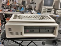
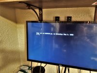
All back together and working. Hey the 5160 has company now!

So, from post #32, you noted that the 623MF multi-function card contains an Oki M5832 RTC chip (or maybe sometimes, an equivalent was fitted).I just purchased an IBM 5150 which has this Lung Hwa 623MF Multifunction card mention above. It appears to be 100% functional, at least in terms of RAM, serial port and parallel port. It passed all tests in Check-It. The RTC battery was dead though and I replaced it. But I have been unable to find any documentation or software in regards to setting the clock. I tried my AST software with it and also the PII-125 from "minuszerodegrees.com". Neither work. Does anybody have any documentation or software for this card? I'd appreciate any info or help anyone can provide. Thanks!
Must be. 'Thompson, Harriman and Edwards' is on the floppy label, and on the card's FCC sticker.I'm also attaching files & disk image (both same files) from the floppy that came with my 5150, I believe it's the original software for the multi-function card.
Once SETCLOCK.EXE and DATETIME.COM have been confirmed as suitable for the 623MF, I will add the software to [here].Must be. 'Thompson, Harriman and Edwards' is on the floppy label, and on the card's FCC sticker.
Probable use:
- Per [here], SETCLOCK.EXE is used once to set the date/time into the RTC.
- DATETIME.COM put into AUTOEXEC.BAT
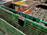
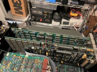
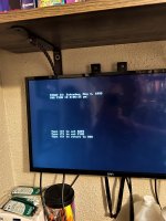
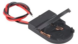
Why? Seems like a step backwards to be honest.Okay gentlemen, that did the trick, my 5150 is now 100% fully restored! I have posted some pictures to show the results. You can see I removed the original hard leaded battery and replaced with a soft leaded 2032 battery holder.
Not sure what you mean there, could you clarify please? Do you mean the battery holder position? The holder is low profile and will not interfere with adjacent boards, non-conductive as well. Allows easy replacement of the battery in the future. Mounting in original location on top didn't quite fit and required mounting it on top of the wire solder joints. I also thought about hard leading another one in there to keep it original. But this would degrade the board in the future when one has to de-solder/solder to replace it again. I am sure there are 101 better ways, but I already had this part and it works good for me.Why? Seems like a step backwards to be honest.
")
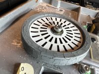
Not me.Which is where I noticed the pulley on drive B was severely deformed and cracked ... and have never seen this before. Have you?
Or perhaps you mean the Y2K compliance? Functionality is what matters to me, not capability. I just want it to be 100% functional and restored to its original glory. This is actually my 3rd IBM 5150 and I do have other RTC/RAM cards I could install that are Y2K compliant. But this is the one that came with this machine originally, so I'd like to keep it that way as long as possible. Call me crazy, I don't care. If I wanted capability, I wouldn't be using/collecting 1980's computers LOL.Why? Seems like a step backwards to be honest.
I mean why didnt you just put a new battery in the original battery holder?Not sure what you mean there, could you clarify please? Do you mean the battery holder position? The holder is low profile and will not interfere with adjacent boards, non-conductive as well. Allows easy replacement of the battery in the future. Mounting in original location on top didn't quite fit and required mounting it on top of the wire solder joints. I also thought about hard leading another one in there to keep it original. But this would degrade the board in the future when one has to de-solder/solder to replace it again. I am sure there are 101 better ways, but I already had this part and it works good for me.