• Please review our updated Terms and Rules here

Getting a SuperPET online

Ral-Clan

Experienced Member
Joined
Jul 15, 2016
Messages
194
Location
Ontario, Canada
Hi,

I'm trying to get a SuperPET/CBM8032 online. So far I've got the following equipment connected:

SuperPET internal serial port <---------> straight-through 25-pin serial cable <-----------> Jim Drew RS-232 wifi modem

My data storage devices are a datasette and a Tynemouth Software PET MicroSD.

Problem is, now I can't find any software that can work with this setup!

The SuperPET originally came with an Editor (on disk) that ran under the 6809 CPU. This editor could act as a Terminal programme. I have the .d80 disk image.
Unfortunately, the SuperPET in 6809 mode will only load SuperPET disks from a 8000 series drive (I believe), or maybe any other real CBM floppy drive. The MicroSD device I have doesn't truly emulate a CBM drive so it doesn't work in SuperPET mode.

I understand that the SuperPET's on-board RS-232 port CAN be accessed by the 6502, but I am unaware of any terminal software that runs in 6502 mode that also supports the SuperPET's on-board RS-232 serial port.

Does anyone know of a solution to this problem? Otherwise I'm going to have to buy a User Port wifi-modem (which seems to be what most PET terminal programs expect).

Thanks,
Ral-Clan

UPDATE:

I found this software disk image: telecom.d80, which claims to have both 6502 and 6809 SuperPET terminal software.

I was able to run the software SUPERCOM.BAS6 from that disk in the VICE emulator, and it ran and showed a menu of parameters. However, when I try to LOAD and RUN the same software on my real SuperPET, the computer just hangs after RUN<enter> before displaying the software's menu. Only a hard power cycle resets the computer. This makes me wonder whether the ACIA chip in the computer is faulty.

I'm a little out of my depth on this - so any help would be appreciated.
 
Last edited:
First thing is: do you know your SuperPET is working OK as a machine?

The second thing is: you can drive the ACIA from BASIC via PEEK and POKE statements to see if it works.

You should also be able to write your own 'terminal emulator" this way. Not pretty, but it should work.

Dave
 
The manual for the 6551 ACIA can be found here: https://swh.princeton.edu/~mae412/HANDOUTS/Datasheets/6551_acia.pdf.

The 6551 ACIA starts at I/O address $EFF0 (decimal 61424) and occupies four (4) addresses.

The TX/RX data buffers are at $EFF0 (61424).
The STATUS register (read only) is at $EFF1 (61425).
The COMMAND REGISTER is at $EFF2 (61426).
The CONTROL REGISTER is at $EFF3 (61427).

By PEEKing and POKEing at these addresses, we should be able to manually program the ACIA and transmit characters to your modem. If we loopback the TX/RX lines we should be able to receive what we send.

Dave
 
The CONTROL REGISTER specifies the number of stop bits, the number of data bits, where the receiver clock is sourced from (use the Baud Rate Generator = '1'), and the desired BAUD RATE. All of the bits of the CONTROL REGISTER are associated with the serial parameters of the communications link.

The COMMAND REGISTER controls the parity of the serial communications link. In addition, it controls ECHO, Tx and Rx interrupts (do not use interrupts for now), and the state of the /RTS and /DTR modem control signals on the RS232 interface.

The STATUS REGISTER indicates the presence of serial errors, whether the transmitter is available to accept a new character, whether the receiver has acquired a character, and the state of the /DSR and /DCD modem control signals on the RS232 interface.

The DATA register (read = Rx data buffer, write = Tx data buffer) should be obvious.

I would suggest ignoring the modem control signals for now, unless your WiFi interface requires them.

I thought this sounded familiar. I see you posted in 2018... My posts are still relevant in that thread. In particular the ROM Setup command (found on page 59 of http://dunfield.classiccmp.org/pet/spmanual.pdf) and the TALK command in the microEDITOR (the same manual).

Dave
 
Last edited:
Unfortunately, the SuperPET in 6809 mode will only load SuperPET disks from a 8000 series drive (I believe), or maybe any other real CBM floppy drive. The MicroSD device I have doesn't truly emulate a CBM drive so it doesn't work in SuperPET mode.
The PetSD with Andre Fachat's XD2031 software supports the SuperPET Waterloo environment just fine. I'm currently building up a CBM-SDmini and will check if that supports it as well.
 
Unfortunately, the SuperPET in 6809 mode will only load SuperPET disks from a 8000 series drive (I believe), or maybe any other real CBM floppy drive. The MicroSD device I have doesn't truly emulate a CBM drive so it doesn't work in SuperPET mode.
The SuperPet requires any Commodore dual floppy drive. It wants the program disk in one drive and the data disk in the other. Offhand I don't know which drive number (0: or 1: ) holds the program/boot diskette.
I thought one of the SD disk emulators designers was looking into modifying their emulator software to handle this by ignoring the drive number.
 
A quick update. I've had some success loading SuperPet software from the SD device. I've also discovered old copies of a newsletter called the Superpet Gazette, which are a wealth of information about the 6809 board's serial port.

The newsletter told me how to get into the SuperPet's monitor mode, where you can press p to enter the terminal mode to the serial port. You can also do this by loading the micro-editor, and then using the TALK command to put it into Direct connection with devices on the serial port.

My only problem now is that I get no response from the rs232 Wi-Fi modem to such commands as ATI or ATDS=1. Not even garbled text, which one would expect if the baud rate was mismatched between the modem and the serial port.

So now I have to determine whether the SuperPet's serial Port is working, or the cable is properly wired, or the Wi-Fi modem is working.

The first thing I'm going to try is hooking up an old US Robotics modem to the port to see if it responds to any AT commands. If it does then I know it's a problem with the Wi-Fi modem. If not then I'll trace it back from there. I doubt it's a problem with the cable because it's a simple 25 pin straight through serial cable, and I've tried two different ones. Some articles on the SuperPet's serial Port mentioned I might need to build a loopback cable, but I'm not sure it's needed in this case yet, because I don't know if the Wi-Fi modem delivers all the signals needed.

Screenshot_20240712_232624_Firefox.jpg
I have yet to try poking the ACIA chip registers cuz I'll have to do a bit of reading and research to understand how to do that. Easiest things first.
 
Last edited:
The CONTROL REGISTER specifies the number of stop bits, the number of data bits, where the receiver clock is sourced from (use the Baud Rate Generator = '1'), and the desired BAUD RATE. All of the bits of the CONTROL REGISTER are associated with the serial parameters of the...
The super pet has a built-in serial port settings utility in ROM. I assume I wouldn't need to poke these values into registers if I have this user interface method to rely on.
 
I did mention about the ROM serial port Setup command and the TALK command of the microEDITOR utility back in post #4.

>>> I assume I wouldn't need to poke these values into registers if I have this user interface method to rely on.

Correct. I mentioned the PEEK and POKE commands if you wanted to write your own test programs in BASIC.

Let's keep it simple to start with...

Put all of your modems to one side. All we need to do first is to test the SuperPET and the cable...

Have you made a cable up as shown in post #7? In particular, pins 4 to 5, and 6 to 8 to 20 should be connected together as shown.

Pins 2 and 3 are transmit and receive respectively. Connect pins 2 and 3 together temporarily.

If you now use the ROM Setup command (any serial parameters should do) and the microEDITOR TALK command, you should get an echo of whatever you type. If not, we have a problem with the SuperPET to diagnose.

If you get the echo, disconnect pin 2 from pin 3. The echo should now stop (thus indicating that our characters are - in deed - going via the serial port).

Does this work?

We can worry about the modem aspect later. Divide an conquer...

Dave
 
Yes, I used to make a living out of fixing communication issues in the dim and distant past.

Most of the work was either RS-232 or 20/60 mA current loop issues. The simplest of all links...

Dave
 
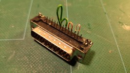
Well I built the loop back connector that Daver2 suggested. It's not pretty but it works.

20240714_222029.jpg

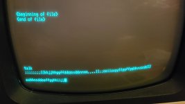
And I get an echo!

20240714_223151.jpg

So what do you suggest I do next? Extend the transmit (2) and receive (3) lines and pins 1 and 7 out to an external connector for the modem? Thank you.
 
So we know for absolute certainty now that the SuperPET and the serial port is OK.

Can you post a link to the manual for your WiFi modem so we can see how it is supposed to be wired up. It is just a possibility that the modem may require the hardware handshake lines - so the cable needs to match the modem.

Dave
 
I have a wimodem232:


The manual can be obtained by choosing the right tab under the picture of the modem.

Claimed on that page:

"The WiModem232 controls ALL of the standard RS-232 lines: Rx/Tx, RTS/CTS, DTR/DSR, and DCD all at the same time. This means that you can use the WiModem232 to run a BBS!"
 
Last edited:
The manual has gone from the link though.

Yes, it mentions links and (I would also assume) there is a firmware configuration required also.

I would start off with the 'hardware' loopback plug in the SuperPET - and just pins 2, 3 and 7 brought out and wired to the modem.

We have to work out which side is transmit and which side is receive (i.e. we need to get the pin 2 and 3 wires round the right way). You should be able to use a multimeter (set to DC volts) and measure the voltage between pins 2 - 7 and 3 -7 on both the SuperPET and the modem ends.

Post the voltages you read:

SuperPET pins 2 to 7 = ???V.
SuperPET pins 3 to 7 = ???V.

Modem pins 2 to 7 = ???V.
Modem pins 3 to 7 = ???V.

Dave
 
The manual has gone from the link though.

Yes, it mentions links and (I would also assume) there is a firmware configuration required also.

I would start off with the 'hardware' loopback plug in the SuperPET - and just pins 2, 3 and 7 brought out and wired to the modem.

We have to work out which side is transmit and which side is receive (i.e. we need to get the pin 2 and 3 wires round the right way). You should be able to use a multimeter (set to DC volts) and measure the voltage between pins 2 - 7 and 3 -7 on both the SuperPET and the modem ends.

Post the voltages you read:

SuperPET pins 2 to 7 = ???V.
SuperPET pins 3 to 7 = ???V.

Modem pins 2 to 7 = ???V.
Modem pins 3 to 7

For the manual....see attached file.

I will try the other things you suggested.
 

Attachments

  • wimodem232_manual.pdf
    892.4 KB · Views: 2
Thanks for the manual. I see the links you were referring to...

How are the shorting links set on your particular board?

I wouldn't propose that you play with these. We should be able to sort out any hardware handshake that the modem requires via the serial connector.

Dave
 
Sorry it's possible you saw an earlier version of my post from earlier today (post #15) before I edited it. The earlier version of my posts erroneously referred to Paul Rickard's Wi-Fi 232 modem. I edited my post quickly to correct the fact that I had a Jim Drew wimodem232, and corrected the hyperlink , but the notification you received from this forum probably still showed you my previous incorrect posting prior to editing.

Not sure that Jim Drew modem has these configuration shorts you mentioned. I know the Paul Rickards modem does.
 
Back
Top