Some of the following you will know, but it is important that we are 'on the same page':
In your computer, there are what could be called 'standard' addresses, and there is another form of addressing called I/O ports. I/O ports are sometimes called I/O addresses. Both utilise the address bus.
* C800h and D800h are 'standard' addresses. The XT-IDE and XT-CF cards use 'standard' addresses for the ROM (EEPROM) circuitry.
* 300h and 320h are I/O ports. The XT-IDE and XT-CF cards use I/O ports for the circuitry that interfaces with the IDE device (hard drive or CF).
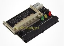
With respect to that, a diagram showing the XT-IDE/XT-CF is at [
here]. They are different functionalities. In fact, the designers of the original XT-IDE card could have produced two cards, a ROM card, and a drive card. Instead, they did the logical thing, which was to put both functionalities onto one card.
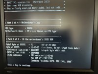
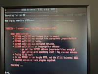
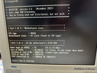
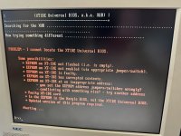
The XT-IDE/XT-CF is somewhat unique, and that is why it needs the XTIDE Universal BIOS (XUB) to 'control' it. When the IBM 5170 starts, the POST will find and execute the initialisation code in the XUB. That initialisation code will do some things, including putting into place, INT13H support for the XT-IDE/XT-CF. DOS will use the INT13H support to interact with the IDE device.
The XUB does not use the hard drive number in the 5170's CMOS SETUP.
If, for whatever reason, the XUB is not executed at POST time, there is no INT13H support put in place for the XT-IDE/XT-CF.
You need to work out why the XUB is not getting executed during POST time. We know that it happens in an IBM 5170. So, is the ROM/EPROM functionality on your card faulty, or is there a motherboard fault, or is there an address conflict! Since the XUB is in the ROM/EEPROM, if an address conflict, it has to do with the 'standard' addresses.
As I mentioned earlier, you need to take CheckIt 'with a grain of salt'.
When you use GSETUP (or whatever) to set the hard drive type in CMOS SETUP to a non-zero setting, you are informing the motherboard BIOS that a 'standard' AT-class MFM controller, or 'standard' AT-class IDE controller, is fitted, and that the motherboard BIOS is to provide INT13H support for it and its attached hard drive.
Certain hard drive controllers are not in that category. E.g. SCSI card. E.g. XT-IDE/XT-CF card.
You need to work out why the XUB is not getting executed during POST time.