• Please review our updated Terms and Rules here

GSETUP regarding expanded memory for IBM 5170

Each time using either the IBM BIOS or Quadtel BIOS to configure the CMOS to accommodate the added 128-KB additional memory; the BIOS would display a 201 and 164 memory error until the card was removed and reconfigured to reset to 512-KB for Base and 0 for any Extended memory settings.
Considering post #40, maybe you think that your card provides {conventional=xxx, extended=yyy} but it is providing something else.

( Or is there some kind of addressing problem on the motherboard. )
 
I can't see how a mistake would brick the 5170, but I will create U17+U37 images (configured for your XT-CF-lite rev.2, sitting at I/O 300) then DM them to you.
ROM images sent.

The source BIN file came from Lo-tech's web page on the XT-CF-lite rev.2, at [here]. The XUB version is R566, which is very old, and has bugs (but not bugs that would stop the XUB splash/banner text appearing). You could get this going, then look at an XUB upgrade.

Mission 1 of 2: Presentation of XUB splash/banner text

I tested the sent ROM images on my 5170 motherboard, of type 3, like yours. Into sockets U17 and U37. At power-on time, the XUB's splash/banner text appeared.

Mission 2 of 2: Ability of XUB to communicate with IDE circuitry

The XUB's splash/banner text indicated no master IDE device, which I expected, because I had no compatible XT-CF card plugged into the motherboard.

'Compatible = compatible with the controller type of 'XT-CF' that is configured in that copy of XUB.

But I have a compatible card, a 'Sergey's XT-CF-Lite V4.1'. Card set to: EEPROM=D0000h, I/O=300h. I disabled the card's EEPROM via the applicable switch. Disabled because I did not want two copies of the XUB running (One at D0000 and one at E0000). I attached a wiped 32 MB CF onto Sergey's card.

I plugged Sergey's card into my 5170 motherboard, then powered on the motherboard. I saw the XUB find the 32 MB CF on Sergey's card. I then booted to a DOS boot floppy then proceeded to do the FDISK and FORMAT operations against the CF

After that, the 5170 motherboard was booting from the CF on Sergey's card.
 
Considering post #40, maybe you think that your card provides {conventional=xxx, extended=yyy} but it is providing something else.

( Or is there some kind of addressing problem on the motherboard. )
1720635911058.png
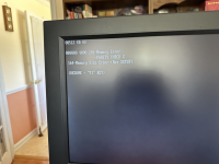
The above picture was made with the Cheetah Combo 1.5-MB card installed. I think the address 080000 is telling me that the error is occurring at the Basie memory address. The Cheetah configuration set the BANK 1 with all switches off, BANK 2 switches 5,7,& 8 were off the others were on, BANK 3 switches 5-8 off 1-4 on, and MODE 1,3, 7, and 8 off the others on. Quadtel BIOS was set to 640-KB for Base and the Extended was set to 1408-KB. I think the 4000 is telling me the 4th column in BANK 2 has a parity error 2 clash the MFM hard drive controller for memory space, I don't know through.
Pressing F1 would allow booting to occur from hard drive.

I'll have to redo the AST error to show it.
 
ROM images sent.

The source BIN file came from Lo-tech's web page on the XT-CF-lite rev.2, at [here]. The XUB version is R566, which is very old, and has bugs (but not bugs that would stop the XUB splash/banner text appearing). You could get this going, then look at an XUB upgrade.

Mission 1 of 2: Presentation of XUB splash/banner text

I tested the sent ROM images on my 5170 motherboard, of type 3, like yours. Into sockets U17 and U37. At power-on time, the XUB's splash/banner text appeared.

Mission 2 of 2: Ability of XUB to communicate with IDE circuitry

The XUB's splash/banner text indicated no master IDE device, which I expected, because I had no compatible XT-CF card plugged into the motherboard.

'Compatible = compatible with the controller type of 'XT-CF' that is configured in that copy of XUB.

But I have a compatible card, a 'Sergey's XT-CF-Lite V4.1'. Card set to: EEPROM=D0000h, I/O=300h. I disabled the card's EEPROM via the applicable switch. Disabled because I did not want two copies of the XUB running (One at D0000 and one at E0000). I attached a wiped 32 MB CF onto Sergey's card.

I plugged Sergey's card into my 5170 motherboard, then powered on the motherboard. I saw the XUB find the 32 MB CF on Sergey's card. I then booted to a DOS boot floppy then proceeded to do the FDISK and FORMAT operations against the CF

After that, the 5170 motherboard was booting from the CF on Sergey's card.
I, too, have the Sergey's card, which I got about 3 years ago from eBay. Sergey's card never worked with the AT&T 6300 that I was using. Of course, I think that someone from the forum told me the addressing for the AT&T was reversed, however, the LowTec's BIOS made it possible for the AT&T to have a 2-GB hard drive. I put these into my other AT&T's including a 80286 version as secondary drive. None of the CF's boot, however. They have the configuration sys files and command.com. I think I read on the forum that these CF drives were too fast for the motherboards and that was why they never would boot.
 
The above picture was made with the Cheetah Combo 1.5-MB card installed. I think the address 080000 is telling me that the error is occurring at the Base memory address.
At [here] is a description of the 201 error.
So:

Address: 080000 hex = 524288 decimal = 512 KB
Data: 4000 hex = 0100000000000000 binary = bit 14

Only one bit in error. There is a very good chance that the cause is a faulty RAM chip. The card's documentation is expected to inform you of which chip that corresponds to. Bit 14 in the card's bank 0 (but that presumes that the card maps its RAM starting at its bank 0). The card may have even been supplied with a card-specific diagnostic tool which will test the card's RAM and display a diagram showing the chip. Point us to the card's documentation if you need assistance.

And it might be that all you need to do is re-seat the chip.

I, too, have the Sergey's card, which I got about 3 years ago from eBay. Sergey's card never worked with the AT&T 6300 that I was using. Of course, I think that someone from the forum told me the addressing for the AT&T was reversed ...
Yes, the PC6300 (Olivetti M24 / Xerox 6060 / Logabax Persona 1600) is a 'special case'.

For example, if I wanted to put my 'VCF XT-IDE Rev 2' card into a PC6300, I would need to reconfigure the XUB on the card: Change controller type from 'XTIDE rev2 or modded rev1' --> 'XTIDE rev2 (Olivetti M24)'
And reverse that change if I then wanted to put the card back into one of my IBM 51xx machines.
 
I, too, have the Sergey's card, which I got about 3 years ago from eBay. Sergey's card never worked with the AT&T 6300 that I was using. Of course, I think that someone from the forum told me the addressing for the AT&T was reversed,
Yes, the PC6300 (Olivetti M24 / Xerox 6060 / Logabax Persona 1600) is a 'special case'.

For example, if I wanted to put my 'VCF XT-IDE Rev 2' card into a PC6300, I would need to reconfigure the XUB on the card: Change controller type from 'XTIDE rev2 or modded rev1' --> 'XTIDE rev2 (Olivetti M24)'
And reverse that change if I then wanted to put the card back into one of my IBM 51xx machines.
Earlier, you wrote, "I have Sergey's card but it doesn't work. I tried it on a number of different boards and machines with no response."
That would have included your IBM 5150.
There must be a fundamental problem with it. If it doesn't work in your PC6300, that will be primarily because of the fundamental problem, not the PC6300's different byte ordering compared to the IBM 51xx family.

In fact, when I look at the 'Sergeys XT-CF-Lite V4.1' entry at [here], I see that the card is fully 8-bit, and so the differing byte order of the PC6300 is not going to be a problem.

In the entry that I pointed to, note the "A preconfigured image file for the EPROM/EEPROM is at here."
1. Use your EPROM programmer to put that BIN file into the 28C64 EEPROM of Sergey's card.
2. Verify that the card's switches are set for a base I/O address of 300h (Assumption: Nothing else in the IBM 5150 is going to conflict with that).
3. Attached a wiped CF to the card. Wiping just the MBR (the first sector) is enough. You can do that in Windows or Unix or DOS. See [here].
4. Put Sergey's card into your 5150.
5. Have a DOS boot floppy in A:, a floppy that contains FDISK and FORMAT.
6. Power up the 5150 and observe that the XUB displays its splash/banner text, and when you do, press the A key so as to boot to the floppy.
7. Perform the normal FDISK and FORMAT operations against the CF.

If that does not work, create a dedicated thread for it.
 
At [here] is a description of the 201 error.
So:

Address: 080000 hex = 524288 decimal = 512 KB
Data: 4000 hex = 0100000000000000 binary = bit 14

Only one bit in error. There is a very good chance that the cause is a faulty RAM chip. The card's documentation is expected to inform you of which chip that corresponds to. Bit 14 in the card's bank 0 (but that presumes that the card maps its RAM starting at its bank 0). The card may have even been supplied with a card-specific diagnostic tool which will test the card's RAM and display a diagram showing the chip. Point us to the card's documentation if you need assistance.

And it might be that all you need to do is re-seat the chip.


Yes, the PC6300 (Olivetti M24 / Xerox 6060 / Logabax Persona 1600) is a 'special case'.

For example, if I wanted to put my 'VCF XT-IDE Rev 2' card into a PC6300, I would need to reconfigure the XUB on the card: Change controller type from 'XTIDE rev2 or modded rev1' --> 'XTIDE rev2 (Olivetti M24)'
And reverse that change if I then wanted to put the card back into one of my IBM 51xx machines.
Regarding the bit-14, the Cheetah users manual doesn't have a troubleshooting chapter. I did use the example's shown in Appendix B of the manual as the method to setup the dip switches on the board. However, there is a typed note release that I didn't see when I first setup this board that doesn't counter mine the examples in Appendix B but resets the memory on motherboard to 256-KB with zero extended memory. Rebooting the system and using the setup to correct for the 256-KB rather than the 512-KB. The release note then recommends the use of the CSSETUP application and logging the results. I'll have to compare this with the Appendix B setting as it may be different. The release note then adjusts the Cheetah card to for 384-KB and the expanded memory to 1152-KB and setting this using the setup procedure. They recommend using a FORCE application included with the software disk, which is intended to force application programs to use the Cheetah card memory above the 256-KB limit on the motherboard. There is a cdisk utility to provide a virtual disk should I need it.

I have four operational AT&T 6300's. Three of the four accepted the Lo-Tek CF cards without any problem. All I needed to get the Lo-Tek's to work was to set the addresses for 320h and D800 and the Lo-Tek worked without a problem The one AT&T 6300 that rejected the Lo-Tek as a special controller made by a company called Prestor is the cause of the rejection. The design of this Prestor controller was to adjust the cylinder size of the hard drive to increase it's physical storage to nearly 2 times it's original value. So for example, a 40-MB hard drive would appear to be 77-MB using the Prestor for drive C and D. The addressing for the Prestor interferes with the C800 and D800 addresses, which of course interferes with the Lo-Tek. Maybe the Sergey card would work here with the corrected PROM. The Lo-Tek works with my AT&T 6300 Plus and IBM 5150; 2-GB on an IBM 5150 is pronominal volume of storage.

The Lo-Tek doesn't work with my 5162 clone and standard IBM 5170. Of course, with your help I think I will be able to get the IBM 5170 to work with the Lo-Tek or the Sergey Card. The IBM 5162 has an AMI AT motherboard and uses a generic IDE controller with a Chinese made IDE-CF adapter that doesn't support the master/slave combination IDE-CF adapters that are sold on eBay. The IDE-CF card does boot the system. I unfortunately cannot find another one of these adapter cards. I'd like to add storage if possible.
 
Last edited:
Earlier, you wrote, "I have Sergey's card but it doesn't work. I tried it on a number of different boards and machines with no response."
That would have included your IBM 5150.
There must be a fundamental problem with it. If it doesn't work in your PC6300, that will be primarily because of the fundamental problem, not the PC6300's different byte ordering compared to the IBM 51xx family.

In fact, when I look at the 'Sergeys XT-CF-Lite V4.1' entry at [here], I see that the card is fully 8-bit, and so the differing byte order of the PC6300 is not going to be a problem.

In the entry that I pointed to, note the "A preconfigured image file for the EPROM/EEPROM is at here."
1. Use your EPROM programmer to put that BIN file into the 28C64 EEPROM of Sergey's card.
2. Verify that the card's switches are set for a base I/O address of 300h (Assumption: Nothing else in the IBM 5150 is going to conflict with that).
3. Attached a wiped CF to the card. Wiping just the MBR (the first sector) is enough. You can do that in Windows or Unix or DOS. See [here].
4. Put Sergey's card into your 5150.
5. Have a DOS boot floppy in A:, a floppy that contains FDISK and FORMAT.
6. Power up the 5150 and observe that the XUB displays its splash/banner text, and when you do, press the A key so as to boot to the floppy.
7. Perform the normal FDISK and FORMAT operations against the CF.

If that does not work, create a dedicated thread for it.
I could experiment with the 5150 to see if Sergey's card with improved PROM would work. I'd have to let you know.
 
Before i setup the experiment of installing and configuring the Cheetah Combo card into my IBM 5170 as shown below; I reconfigured the IBM 5170 motherboard at jumper 18 to lower the Base RAM to 256-KB. I then powered on and corrected the CMOS settings to accommodate the lower base memory to 256. In addition, the extended memory is still at 0.

I followed the release note regarding the Cheetah Combo card with the following settings as was shown in the user's manual under Appendix B example 1 where 256-KB resided as the base memory and the extended memory was set to 0. The following setup was introduced:
  1. Bank 1 switch 1 is off and the other 7 was a don't care X as was shown in the manual while the CHSETUP basically showed all 8 switches as being off
  2. Bank 2 switch 5 is off and switches 7,8 were don't care X as was shown in the manual while the CHSETUP basically showed 5, 7, & 8 as being off with the remaining 5 switches on.
  3. Bank 3 switches 5,6 are off and switches 7, 8 don't care X as was shown in the manual while the CHSETUP basically showed switches 5-8 as being off and the remaining 4 switches as being on.
  4. Mode switches 1-3 were off and switches 4-6 were on with switch 7 as don't care and switch 8 was on. CHSETUP basically showed the same setup.
When the IBM 5170 was powered up I got a Parity Check 2 as error and the machine failed to proceed any further. There isn't any mention in the manual regarding the Parity Check. Now, I am not using the IBM BIOS right now. I left the Quadtel BIOS in and I haven't populated the U17 and U37 chips as yet. I presume the Parity Check error is originating from the Quadtel. Question is what is the Parity Check 2 and how does it relate the Cheetah Combo card? I assume the error is coming from the Cheetah card itself.
 
When the IBM 5170 was powered up I got a Parity Check 2 as error and the machine failed to proceed any further. There isn't any mention in the manual regarding the Parity Check. Now, I am not using the IBM BIOS right now. I left the Quadtel BIOS in and I haven't populated the U17 and U37 chips as yet. I presume the Parity Check error is originating from the Quadtel. Question is what is the Parity Check 2 and how does it relate the Cheetah Combo card? I assume the error is coming from the Cheetah card itself.
The 'PARITY CHECK 1' and 'PARITY CHECK 2' messages are generated by the motherboard BIOS.
PARITY CHECK 1 = RAM parity error occurred on motherboard.
PARITY CHECK 2 = RAM parity error occurred on RAM card. (The card flags that to the motherboard via a pin on the ISA connector.)

The Quadtel BIOS has probably copied the IBM BIOS. You could always put the IBM BIOS back in to confirm that.

When there is an associated 201 error, the 'PARITY CHECK 1' or 'PARITY CHECK 2' message is mostly superfluous. E.g. 201 error points to address 1.8 MB, and in the 5170, RAM at that address can only possibly be supplied by a RAM card. Thinks get tricky when the PARITY CHECK message has no associated 201 error.

Regarding the bit-14, the Cheetah users manual doesn't have a troubleshooting chapter.
Assisting the user, some cards have printing on them to indicate the banks and bits.
Lacking that, and no 'chip layout' information in the manual:
- In case of poor connection, try reseating all RAM chips on the card.
- Experiment by swapping chips about. (E.g. I just saw the 201 error's address or bit change when I swapped over one set of 4 chips for another set of 4. Clearly, the problem chip is one of the eight chips. Etc.)

The above picture was made with the Cheetah Combo 1.5-MB card installed.
What is the exact model number of this Cheetah card, and is the manual online?
I see a manual at [here], but that is a 2.5 MB card.
 
The 'PARITY CHECK 1' and 'PARITY CHECK 2' messages are generated by the motherboard BIOS.
PARITY CHECK 1 = RAM parity error occurred on motherboard.
PARITY CHECK 2 = RAM parity error occurred on RAM card. (The card flags that to the motherboard via a pin on the ISA connector.)

The Quadtel BIOS has probably copied the IBM BIOS. You could always put the IBM BIOS back in to confirm that.

When there is an associated 201 error, the 'PARITY CHECK 1' or 'PARITY CHECK 2' message is mostly superfluous. E.g. 201 error points to address 1.8 MB, and in the 5170, RAM at that address can only possibly be supplied by a RAM card. Thinks get tricky when the PARITY CHECK message has no associated 201 error.


Assisting the user, some cards have printing on them to indicate the banks and bits.
Lacking that, and no 'chip layout' information in the manual:
- In case of poor connection, try reseating all RAM chips on the card.
- Experiment by swapping chips about. (E.g. I just saw the 201 error's address or bit change when I swapped over one set of 4 chips for another set of 4. Clearly, the problem chip is one of the eight chips. Etc.)


What is the exact model number of this Cheetah card, and is the manual online?
I see a manual at [here], but that is a 2.5 MB card.
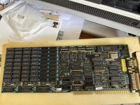
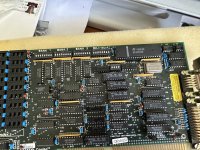
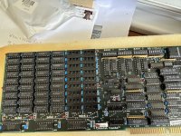
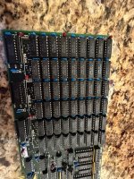
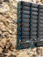
Modem7, I have attached the user manual from my Cheetah Combo Extended Memory Card. The card is 1.5-MB with both serial and parallel ports that can be configured. I could zip the files from the enclosed floppy disk that came with the card, if minuszerodegrees website wishes to host this model, IMG_5073.jpegIMG_5076.jpegIMG_5077.jpegif minuszerodegrees website wishes to host this model. I have included pictures of the card before I populated it with the added 512-KB pf RAM. Notice that the brown caps are Titanium. One of those could be defective even though there is no evidence of that from the pictures.

I can remove the Quadtel BIOS and reintroduce the IBM BIOS to the 5170. Since the 5170 machine worked with the RAM set to 256-KB before the entry of the Cheetah card, I think you're right the problem exists on the Cheetah card. When I received the card, the card was populated with 1-MB of RAM 120-ns. I populated the third bank with the 512-KB of RAM, also 120-ns. There are different manufacturer's of the RAM populated on the card. My additions were NEC. However, I don't think the brand of chips are the issue.

The issue here is if there is a defect with the card, there isn't a way to detect it with the few tools available to diagnose the problem and fix it.
 
I have attached the user manual from my Cheetah Combo Extended Memory Card.
You forgot to attach it.

Assisting the user, some cards have printing on them to indicate the banks and bits.
I can see that in the photos. The banks are clearly labelled.

The bits are labelled as well. To the right of the 'LOW' column of bank 3 are 'PH', '0', '1', 2','3', ... '7'. That identifies half of each bank, the low bits. I am guessing that the printing that identifies the high bits are at the far left of the card. Are you able to supply a photo of the far left side of the card?

I could zip the files from the enclosed floppy disk that came with the card, if minuszerodegrees website wishes to host this model
Yes. It could help someone else down the track.

Notice that the brown caps are Titanium (sic). One of those could be defective even though there is no evidence of that from the pictures.
If the case, that would would likely cause random type symptoms. You have not mentioned random symptoms yet.

My additions were NEC. However, I don't think the brand of chips are the issue.
Not expected to be a problem at all.

The issue here is if there is a defect with the card, there isn't a way to detect it with the few tools available to diagnose the problem and fix it.
You had a 201 error before, pointing to bit 14. Probably a RAM chip. Labelling on the card identifies the bit 14 chip for each bank. So the standard first thing to do is to reseat the bit 14 chips in each bank. If that does not remove the error, go to each bank and swap the bit 14 chip with the bit 12 chip (for example). If the 201 error then points to bit 12, you know that it is a RAM chip causing the problem, and that you have just then narrowed it down to three chips. Etc.

And you can do this in stages. First, configure the card for: one bank of extended memory. So, that is 512 KB of extended memory. Set the CMOS SETUP to {512K base/conventional + 512K expansion/extended}.

If/once that is working, try two banks of extended memory. If/once that is working, try three banks of extended memory. If/once that is working, try a 'split' configuration (topping up the base to 640K and the balance as extended.
 
I guess the manual didn't get uploaded because of it's physical size exceeded the limits of the forum uploads; it's 20-MB. I'll have to find some website that can host the manual and pass on a link to it.

As requested, I made pictures of Bank 1 and the labeling of the chips above the high side of the bank. As can be seen, the labels begin as PL, which must mean parity low. The PL is followed by 8-15 for the succeeding rows.

No random symptoms have been seen.

I think that I have to remove both banks 2 and 3 chips to reduce the card down to say 512-KB of extended memory. I don't see an off switch for banks 2 and 3; so the probability of me not seating these correctly for a second/third time increases when I increase from 512-KB to 1-MB to repopulate bank 2 and conversely from 1-MB to 1.5-MB to repopulated bank 3. In other words the possibility exists for added errors if I can't get the chips re-seated correctly. I have to bear that in mind.

Attached is a page out of the manual (note: the table is from Appendix A, which is a memory address selection switch chart. There is no further explanation given for Appendix A), which shows the setting for the switches for banks 1-3. First, the 5170 is currently setup for 256-KB but can be changed back to 512-KB merely by changing jumper, J18, to accommodate that base memory size of 512-KB. I found using InfoPlus, Checkit and MSD while set at the 512-KB base size there was virtual memory from the base through to 1-MB. In fact MSD showed ROM's occupying the last 64-KB of memory to 1-MB and Checkit as well as InfoPlus stated that there was 435-KB of available memory even though no physical memory existed. So, this 435-KB is virtual memory. Procedure following suggestted changes to the Cheetah Combo card:
  1. Under the first scenario, I have 512-KB of Base memory with added 512-KB of Virtual memory; then using the 512-KB of Extended memory I would use from the table of the attached PDF from the users manual for addresses 160000-17FFFF to set switch setting for Bank 1 switch to achieve 1.5-MB of memory on the machine.
  2. Using the same scenario for the base and virtual memories and populating Bank 2, which would house 1-MB of Extended memory. I would use from the table addresses 1E0000-1FFFFF to set switch settings for Bank 1 and 2 switches to achieve 2-MB of memory on the machine.
  3. Lastly, repeating the scenario and populating Bank 3, which would house 1.5-MB of Extended memory. I would use from the table addresses 260000-27FFFF to set switch settings for Banks 1-3 to achieve 2.5-MB of memory on the machine.
Under those different processes above, I would assume that the system BIOS would be set for Extended memory according to 512-KB, 1 and 1.5-MB while leaving the Base memory at 512-KB. If successful, would the need necessitate adding 128-KB of Bank 1 when virtual memory seems to be in play?

Also, the zip file houses the only files from the Cheetah disk included with the card.

IMG_5424.jpegIMG_5427.jpeg
 

Attachments

You forgot to attach it.


I can see that in the photos. The banks are clearly labelled.

The bits are labelled as well. To the right of the 'LOW' column of bank 3 are 'PH', '0', '1', 2','3', ... '7'. That identifies half of each bank, the low bits. I am guessing that the printing that identifies the high bits are at the far left of the card. Are you able to supply a photo of the far left side of the card?


Yes. It could help someone else down the track.


If the case, that would would likely cause random type symptoms. You have not mentioned random symptoms yet.


Not expected to be a problem at all.


You had a 201 error before, pointing to bit 14. Probably a RAM chip. Labelling on the card identifies the bit 14 chip for each bank. So the standard first thing to do is to reseat the bit 14 chips in each bank. If that does not remove the error, go to each bank and swap the bit 14 chip with the bit 12 chip (for example). If the 201 error then points to bit 12, you know that it is a RAM chip causing the problem, and that you have just then narrowed it down to three chips. Etc.

And you can do this in stages. First, configure the card for: one bank of extended memory. So, that is 512 KB of extended memory. Set the CMOS SETUP to {512K base/conventional + 512K expansion/extended}.

If/once that is working, try two banks of extended memory. If/once that is working, try three banks of extended memory. If/once that is working, try a 'split' configuration (topping up the base to 640K and the balance as extended.
I have the Cheetah Combo Users Manual on Google Drive. Here is the link: https://drive.google.com/file/d/1oL4FHht0PKC55OgXc-QtyC6aRuw4Pt3v/view?usp=drive_link
Modem7, You'll have to let me know if there is permission problems. If so then we'll have to do PM so that you can get access.
 
First, the 5170 is currently setup for 256-KB but can be changed back to 512-KB merely by changing jumper, J18, to accommodate that base memory size of 512-KB.
Technically, that should be, "to accommodate the motherboard memory size of 512-KB".

J18 enables/disables motherboard RAM. With 512KB on the motherboard, J18 is not normally at the '256K' setting. That would be like disabling half of the four populated RAM banks on one of my IBM 5160's. That would be going backwards.

I recommend that you have J18 set at the '512K' setting, then pretend that J18 does not exist.

The manual mentions J18 because what must not happen is the motherboard supplying RAM in the 256K-512K range, and, the Cheetah card set to supply RAM in the same range.
 
I found using InfoPlus, Checkit and MSD while set at the 512-KB base size there was virtual memory from the base through to 1-MB.
The 5170's memory map of the 640K-1M space is at [here].
- Some of that space is for ROM (motherboard ROM, and optional BIOS expansion ROM's)
- Some of that space is for video RAM.
- Some of that space is used by the window of an EMS card (if fitted).
- Some network cards put a block of RAM in here.
- There are going to be areas of 'no memory' (no RAM nor ROM).

That is why the Cheetah manual indicates, "System Memory - DO NOT USE".

I wouldn't call it 'virtual' memory.

The software that you quote is trying to do the best that it can to inform you of what of the 640K-1M space is being used by what in your 5170.

... and Checkit as well as InfoPlus stated that there was 435-KB of available memory even though no physical memory existed.
I would only be surprised if that was reported when both: J18 set to 256K' setting, and, Cheetah card absent. (And any other RAM supplying card.)
In that scenario, there can only be 256 KB present.
 
I think that I have to remove both banks 2 and 3 chips to reduce the card down to say 512-KB of extended memory.
When I get access to the remainder of the manual, things should become clearer. For example, an explanation of the use of the fourth switch block.

I will then be able to provide some test configurations (switch settings on Cheetah card, plus CMOS SETUP settings to use).
 
When I get access to the remainder of the manual, things should become clearer. For example, an explanation of the use of the fourth switch block.

I will then be able to provide some test configurations (switch settings on Cheetah card, plus CMOS SETUP settings to use).
I'll wait to hear from you. Again, many thanks for all your effort to assist me with this machine.
 
Back
Top