modem7
10k Member
The POST reports the first RAM error encountered, then does no more RAM testing. One fixes that error and then sees if the POST detects more, and so on.You're going to love this one. I found that the chip in Bank 1 for what had been Bit 12 moved back to Bit 14 displayed the old error of 80000 4000 201. So, the chip was defective. I replaced the chip thinking, did we get them all; not quite looks like there is a new error message 80008 1100 201. Now the 1100 is signaling bit's 12 and 8 as the sources for new error's.
RAM chips can fail in different ways. Some examples:However, it's the 80008 that has me confused. Is the message saying that I have two errors one in the high bank and one in the low bank?
- Unresponsive ('dead').
- Partially faulty: One or more bits in the chip's cell matrix are faulty.
- Partially faulty: Addressing related problem.
More background: The POST tests using words, not bytes. Because of that, failure address will always be an even number.
E.g. Test word at address 0, test word at address 2, test word at address 4, and so on
Regarding the first example above. The first address of the bank will usually show as faulty. E.g. 80000. However, I have seen the IBM 5170's POST sometimes show the second test address, e.g. 80002
Regarding the second example above. Let's pretend that there is only one faulty cell. If that chip was to be fully tested, it would be discovered that only one cell address fails a read/write test, all the other addresses testing good. The failure address is going to depend on exactly which cell has failed.
So if on one of my 5170's I saw 80010 0002 201, I would say to myself something like, "16 (10 hex) addresses past the start of a bank. That is probably a RAM chip that has a faulty cell somewhere in it." (Not a 'dead' chip.)
The '80008 1100 201' that you are seeing is unusual in that there are two bits (i.e. two chips) showing up at exactly the same 'not the first' address.
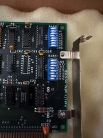
We know now that your Cheetah card is providing the 512-640K addresses space from its bank 1. I suggest that you swap out the bits 12 and 8 chips of bank 1, with chips from another bank (which assumes that the chips in the other bank are good). See how that goes.