• Please review our updated Terms and Rules here

Help getting a PET 4016 running again - for a beginner!

timleach

Member
Joined
Jul 28, 2024
Messages
19
Location
UK - East Anglia
Hi everyone! I’ve recently come into possession of a Commodore PET 4016, in quite good condition, and I’d really like to see if I can get it working.

PXL_20240713_202728675
PXL_20240713_2027286751920×2550 353 KB
PXL_20240713_220313602
PXL_20240713_2203136021920×2550 340 KB

PXL_20240713_220333394
PXL_20240713_2203333941920×1446 259 KB


Problem is, I don’t really know what I’m doing! I’ve never done this kind of maintenance before. I studied electronics in school, so I know how to use a multimeter and a soldering iron, and I know the difference between resistors and transistors and capacitors and stuff, but I’m completely at a loss when it comes to diagnosing problems with a big complicated system like this.
So, I’d really appreciate some help trying to get this lovely machine working again. I’ve tried to read guides online, but they use language I’m unfamiliar with and skip out large steps that I need.
Here’s what I’ve done so far:
  • Visual inspection: looks good, inside and out
  • Plug it in and turn it on: nothing, not even a piezo beep. Occasionally (about 50% of the time) when I turn it on I hear a quiet “thunk” from the power supply area, but that’s the only different thing that happens
  • Check fuse: fuse is intact and conducting
  • Check voltages coming out of power supply: now here’s the weird part.
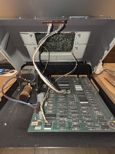
The schematics for the PET don’t seem to have an obvious “this is what the voltage is supposed to be for each pin” diagram, instead just referencing the colour of the wires. (I’ve attached a picture of the power supply above). I’m assuming that if we take black as GND, then:
  • red = +5V
  • blue = -5V
  • brown = +12V
But this isn’t what I find. Instead, I got these readings (relative to the black wire at pin 5):
  • Pin 4 (brown): -0.05V
  • Pin 6 (brown): -0.05V
  • Pin 7 (blue): +7.13V (why is it not negative?)
  • Pin 8 (blue): +7.46V
  • Pin 9 (brown): +9.65V
  • Pin 10 isn’t connected to anything, so I don’t want to connect my multimeter to it directly (maybe this isn’t a concern, but I’m playing it safe)
  • Pin 11 (brown): fluctuates around +10V
Finally, there’s a capacitor next to the power supply, connected to a bundle of black and red wires. I measure the voltage across this capacitor to be +9.26V.
So, those voltages don’t seem right, but I don’t really know what to do about that. If the power supply is faulty, can I get by somehow by using a replacement modern power supply that provides +12V, +5V, 0V and -5V, or would I have to somehow track down a replacement?
Sorry for the long read, I hope this is of interest to the people here! I look forward to any guidance you all have for me
:blush:
 
Never fear, there are many experts here that will be able to help you.

To get started the voltages coming off of the transformer are AC. The 3 TO3 silver packages in the heat sync are the voltage regulators. I recommend checking the voltages on the ics on the board. Look up a data sheet for one of the 74 series or the long row of ram on the left and see where vcc and ground are. Until you get a good beep code you might want to disconnect the wire going to the vdu - video board to prevent possible damage from a bad horizontal drive signal. It's the connector in the very front on the left. J7 on my 4032 IIRC

Best of luck, it's very satisfying when they come back from the dead.

Edit: look up the schematics on zimmers and look for the caps for the 3 voltages. They are also a good point to test.

Mine had good voltages but had issues with the caps in the reset circuit around the 555 timer so, once your voltages are good that's a place to check next.

I'm away from home so i can't look things up but 9 ish volts sounds about right for the input into the 5v regulator
 
Last edited:
First of all, as this is your first post, welcome to VCFED.

It is unfortunate that you turned it on though. Sometimes the black magic smoke gets let out of the box and it doesn't work again! Fortunately, in your case it didn't!

Firstly, what is the part number on the PCB? We can then identify the correct schematic diagram for your machine.

Secondly, you need to understand that the external 'power supply' is just a transformer - so the voltages from this are AC not DC.

The AC voltages pass from the transformer to the main logic board, where the voltages are full-wave rectified. The large capacitor is on the INPUT DC rail BEFORE the +5V regulators. +9V (or so) for the voltage across this capacitor sounds about right.

All the DC voltage regulators are on the main PCB. Once we have determined which board you actually have, we can identify the capacitors that should have the regulated DC supplies across them (e.g. +5V, +12V and -5V).

Do you have a logic probe? These are quite cheap to buy.

Do you have access to an oscilloscope?

Dave
 
Thanks for your replies, both of you!

@Mike Brixius, I've done as you suggested and disconnected the J7 wires. Glad we caught that before I've done too much messing around! I've successfully measured the expected control voltages on many of the ICs, so I'm reassured that the board is being powered properly.

@daver2, thanks for the welcome! I'm glad I didn't break it before I'd even started, that would have been very sad!
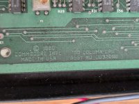
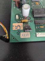
I'm afraid I don't know how to find the PCB's part number -- is it found in either of these two places?
PCB number.jpgPCB labels.jpg
A piece of information that may also help is that I believe this uses Commodore's "universal board", which uses a MOS 6545 as a CRTC. (I was advised to check that from this comment, on a post I made in another forum.)

I sadly don't have access to an oscilloscope, only my multimeter. I don't think that's quite the same as a logic probe, but it's been helpful so far.

I've been able to measure that the RESET pin on the 6502 is correctly being held high, and I'm measuring a voltage on its clock input pin, so something is definitely happening on that pin (though I can't verify it's the expected 1MHz square wave!)

I've tracked down the right schematics on zimmers.net, which has been very helpful for seeing which slot is supposed to hold which IC, but I'm at a bit of a loss as to how to proceed from here, especially without an oscilloscope to properly check all the ICs.
 
If it is an 8032080 then it is indeed a Universal (see here: https://www.zimmers.net/anonftp/pub/cbm/schematics/computers/pet/univ/index.html).

There is also an 8032090 (Universal 2). But, if your board is an '80', then it is the straight Universal.

A multimeter is not the same as a logic probe.

The /RESET pin should NOT be HIGH (totally)!

Clip your multimeter onto the /RESET pin (6502 CPU pin 40) and turn the PET ON. The /RESET pin should be LOW (for about 0.5 to 1.0 seconds approximately) and then should go HIGH. If it goes HIGH immediately you turn the power on, this is not actually resetting the 6502 CPU.

The power supply for the Universal is shown here: https://www.zimmers.net/anonftp/pub/cbm/schematics/computers/pet/univ/8032081-11.gif.

You should measure +5V across C9 and C11 (there are two (2) separate +5V rails).

You should measure +12V across C7.

You should measure -5V across C1.

All of these measurements should be taken relative to 0V/GND (e.g. the black wire (negative side) of the large external capacitor by the transformer).

[Mike identified the three (3) TO3 parts on the heatsink. These are the +12V and the two +5V regulators. There is a much smaller -5V regulator (VR1) on the board with no heatsink. ALL of the voltage rails are required for the correct operation of the PET. A missing -5V rail will upset the Dynamic RAM. The +12V rail is only used by the Dynamic RAM also.].

You can forget using a multimeter on the clock line! You can use a multimeter to measure AC (50/60 Hz) and DC voltages and monitor slow signals (such as the RESET signal). A logic probe can be used for checking logic signals and generally contains an 'invalid' logic level sensor and a pulse catcher function. These can be obtained for a few pounds/dollars and are well worth the investment. After that you need to start thinking about an entry level oscilloscope - but there still is a lot of checks we can do without one.

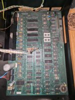
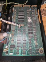
After you have checked the above voltages, can you post a complete photograph of the entire board. Also, are there any WHITE IC sockets fitted to the board? There is a good reason for asking...

Do you know someone who can program an EPROM for you? I have a (free) test program that can be programmed into an EPROM that can replace one of the socketed devices on your board. The problem with having BASIC installed in the PET is that the machine has to work. My test program requires a limited functionality to work - but not the RAM or a large majority of the ROM devices - and can be used to incrementally check things out.

Dave
 
Last edited:
I see from the power plug and general purpuse wall outlets you are probably in the UK ? If you are, you never know, you might be close to @daver2 who is the Forum's PET Detective.
 
Good spot there Hugo...

I am in Worcester (as stated in my posts) but I do commute up the M5 and M6 as far as Lancaster on a regular basis. I am currently sat in a motorway service station on the M6 on the way home...

If you are in the UK, and live not too far away from where I 'hunt', I would be happy to call in and look at the patient. If this would be of help, I can send you a DM, and we can take that discussion off-board.

I can even bring a logic probe and an oscilloscope with me. You provide the coffee and cake!

Dave
 
Thanks for how comprehensive you're being, I really appreciate the help!!

I measured the voltages across the capacitors, and they're all correct within 0.3V or so. For some, the voltage across was correct (say, 5V), but if I measure both terminals relative to the black wire out of the big power supply capacitor, I measure e.g. 5.3V and 0.3V. I assume this is fine, and it's the voltage across the capacitors that matters?

The 6502's /RESET pin does indeed start off at 0V, but it stays there for much longer than you suggested (I counted between 6 and 8 seconds until it changes to 5V).

I'm afraid I'm not sure how to test the voltages coming from the regulators in the heatsink - are the visible metal parts of them probe-able, or would I have to remove the board to access the underside, where I assume the terminals are?

The smaller voltage regulator seems to be fine - I couldn't find a pinout, but I measured its pins to be -5V, -12V, and 0V in that order from left to right.

I'm exploring options to gain access to an oscilloscope. I can't afford to just buy one right now, but there's a small chance I can set up my raspberry pi to act as an oscilloscope, though I don't know whether the sample rate will be high enough! Alternatively, I live close to a computing history museum, and I wouldn't be surprised if there are some people there with the kit (and the know-how) this job needs.

Here are two pictures I took of the whole board, from slightly different angles:
Mobo1.jpgMobo2.jpg

There are indeed some white sockets here:
  • the 6502 itself is in one
  • UD7 (containing a chip which reads MOS 901498-01 2481)
  • UD11 and UD12 (both empty, but perhaps they're not supposed to be?)
The only other socket on the board is a black one in slot UA3, housing a chip reading MOS 901447-10 2781.

I don't currently know anyone who can program an EPROM for me, but I have a raspberry pi and a breadboard, so it's possible I can wire an EPROM up on the breadboard and write something to get the Pi to program it?

Good spot, I am indeed in the UK! It's a very kind offer to meet up with your kit, but sadly I'm in Cambridge, which looks to be a 3 hour drive out of your way (and I myself can't drive). Still, if you're ever out in East Anglia, shoot me a DM and I'll gladly take you up on your offer (and provide as much coffee and cake as you like)!

The forum is telling me that I'm still a moderated user and can't send DMs, so hopefully that ban will be lifted if it comes to that.
 
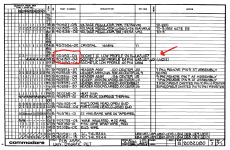
EDIT: I have realised that the below part 904150-4 almost certainly refers to the socket, not the IC. I found the actual two part numbers in the expected places elsewhere in the schematics. I'll leave the post here to document the mistake, though!

Now that is interesting.

I've looked at the parts list in the schematics (because I was curious about what would fit into those empty UD11 and UD12 sockets) and I discovered that they are usually the same part that goes into UA3 and UD7, which are the other two socketed IC slots on the board besides the 6502.

Weirdly, though, the part numbers printed on those ICs are different to the one in the schematics:
  • in slot UA3 we find part 901447-10
  • in slot UD7 we find part 901498-01
Components.png
Now I don't know if this is evidence of some strange aftermarket modification or what, but it may be useful in diagnosing.

I'm going to go through and double-check the part numbers of the other chips now, to see if there are any other discrepancies!
 
Last edited:
Excellent detective work...

>>> Thanks for how comprehensive you're being, I really appreciate the help!!

No problem. That is why we are here...

In post #5 I identified the smoothing capacitors to measure the voltages across for the individual power rails. This should make it much easier than taking the PCB out and messing about.

You need to get to 10 posts to escape moderation and to be able to use Direct Messages. You will get there fairly shortly...

UA3 (901447-10) is the video character generator.

UD7 (901498-01) is the EDIT ROM ($Exxx) and is for BASIC 4, 40 columns, 50 Hz, 4032 computer with a Business keyboard.

This means that all of the other ROMs should match with BASIC 4:

901465-22 ($Fxxx - Kernal ROM - UD6).
901465-20 ($Cxxx - BASIC ROM - UD9).
901465-21 ($Dxxx - BASIC ROM - UD8).
901465-19 or 23 ($Bxxx - BASIC ROM - UD10).

The other two (2) ROM sockets (UD11 and UD12) are option ROMs - so should be empty on a bog standard PET. They can be used to add optional extensions to BASIC.

The white IC sockets are notorious for poor IC pin contact. You may want to remove the IC and spray the IC pins and sockets with DeOxit...

The RESET pulse seems to be a bit long for my liking, but that is easily fixed once we get the PET operational...

Problems could be - poor contact on the white IC sockets, RAM faults or ROM bitrot. After that, we are looking at TTL device failures.

I am (occasionally) in Cambridge (at the computer museum). Next time I go, I will give you a heads-up.

I have to program some 2716 EPROMs for another job - so I will see if I can 'sneak' one in for you with my PETTESTER code on it. It may be a few weeks though...

Incidentally, most of the PET ROM images are archived here: https://www.zimmers.net/anonftp/pub/cbm/firmware/computers/pet/

Dave
 
Last edited:
Apologies for the long gap since my last post - life gets in the way!

That would be great if you could let me know next time you're at the museum. I visited there myself and chatted with one of the people there, who said they have a regular PET guy who comes around (I think he said his name was Alan?) and he'd let me know the next time he was there, so I could bring the PET along.

In the meantime, I'm curious to see if I can get something displaying on the screen using a raspberry pi, just for my own curiosity and to make sure the screen works! I've started a separate thread for that here.

Otherwise, I look forward to hearing from you about these EPROMs, or back from the museum, and I can report back here once we all manage to get it working again!

Tim
 
I have some great news - I've managed to find a friend who has an oscilloscope I can borrow! I'll be able to take some readings this weekend, then - apart from making sure all the clock signals are as we expect, what else should I measure with the scope to check?
 
The 6502 CPU pin 7 is an interesting pin to monitor.

This pin should pulse every time the CPU fetches and executes an instruction.

Dave
 
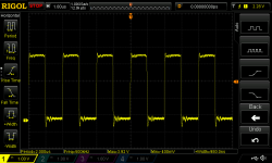
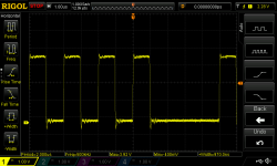
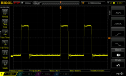
@daver2 you were absolutely right, monitoring pin 7 was very interesting.
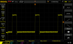
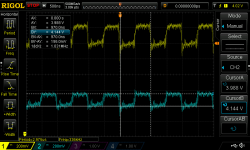
pin-7 (1).pngpin-7 (2).pngpin-7 (3).pngpin-7 (4).pngpin-7 (5).png
It's going high, but irregularly, which makes me think it's actually churning away doing something. I understand different 6502 instructions take different numbers of cycles to complete, so it looks like it's not just doing a NOP over and over!

The weird part is that I took these readings after the computer had been on for a few minutes. My assumption had been that the PET would stop executing instructions once it had booted up, because there's not anything for it to do while it waits for input, right? Although now I think about it, it probably gets itself into a loop while it's waiting for input, because it has to check each row on the keyboard individually, doesn't it?

This is quite perplexing - these readings make the PET look "alive", but the screen isn't displaying anything at all (I tried measuring the voltage on the J7 pins that lead into the CRT, and there doesn't seem to be any signal on them).

Here are some readings when I connected one channel to A0 and one to A1 (pins 9 and 10):
A0 and A1 (1).pngA0 and A1 (2).pngA0 and A1 (3).pngA0 and A1 (4).pngA0 and A1 (5).png
so it even seems like it's loading the instructions from memory.

The oscilloscope has up to 4 channels, but it's a bit tricky to probe the pins because I have to awkwardly hold them all, but are there any pins I could specifically probe, maybe to see what area of memory it's trying to access?
 
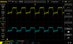
I've just measured the D0 and D1 pins, which has proven to be quite strange:
D0 and D1 (1).png
The signals are really noisy, and don't have any exciting pattern - it's just a 1MHz square wave on both.
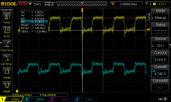
It's also not going between 0 and 5V, either:
D0 and D1 (2).png
D0 is going between 4V and 4.24V (ish), and:
D0 and D1 (3).png
D1 between 3.99V and 4.14V.

I don't know if they're actually both just staying at logical high and oscillating thanks to some other effect (you can see in the A0 and A1 images in my previous post that sometimes the logical high signal varies its voltage).

Hope this is interesting and helpful - I've got the scope for a little while so I can continue to explore this!
 
OK, let's take this in stages. There are a number of pins to check to see what is going on...

The CPU never should stop executing something. As you say, it has to scan the keyboard. It should also be flashing the cursor (and other things) in the background.

As a result, pin 7 will be varying in time depending upon how many clock cycles it takes to execute a particular instruction.

UE12 (74154) divides the 64K memory space up into 4K chunks.

Check UE12 pins 9, 10, 11, 13, 14, 15, 16, and 17 for signs of activity. Some of these pins indicate activity with the screen memory and ROMs.

Also, check UD1/10 (/RAS0), UD5/11 (/CAS1) and UD5/8 (/CAS0) for activity. These pins indicate activity on the DRAM.

If these look sensible, we will have a poke around the CRTC (UB13).

It may be sensible to add a "soft reset" button. Do you have a normally open pushbutton and a 100 Ohm resistor (or similar) available?

Dave
 
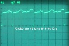
Sometimes you will see voltages in TTL circuits varying between about 3.8 and 4.2 volts. Typically seen on data buses and other shared lines that are controlled by tri-state devices. They are both logic highs. It can make the tops of the square like waves look jaggered and messy. You don't tend to see this sort of thing in cmos circuits, because their output stages actively pull the lines to a solid logic high close to 5v or low to ground. In any case it does not mean there is anything wrong. Only if the voltage for TTL goes to some intermediate or "no man's land" logic level between say 1 and 1.4V it can indicate some contention or hardware issue where two gate outputs are fighting on the same line.

I have attached a photo of a /cas0 signal from a PET, and this sort of thing, riding on a logic high level, is normal in many computer TTL circuits.
 

Attachments

  • Cas0.jpg
    Cas0.jpg
    54.3 KB · Views: 1
Last edited:
Alright, some results!

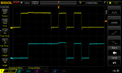
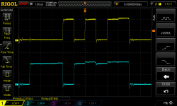
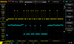
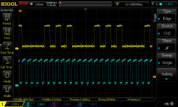
UE12: pins 9, 10, 11, 13, 14, and 15 are always high, with no activity. Pins 16 and 17 have intermittent activity that seems to follow actions on the 6502's pin 7:
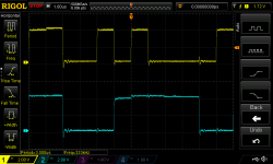
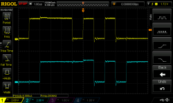
pin16.pngpin17.png
(Top, in yellow, is 6502 pin 7 for both. Bottom, in blue, is UE12 pin 16 for the first image and pin 17 for the second.)

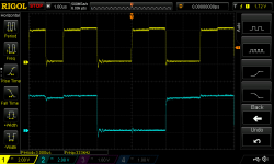
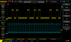
UD1: Activity on pin 10, seemingly independently of the CPU SYNC:
UD1 pin 10 (2).png
(Again, CPU SYNC on top, UD1 pin 10 on bottom)

UD5 pin 11 seems to be high all the time. UD5 pin 8 has some activity:
UD5 pin 8.png

So clearly some DRAM usage is happening, but given that most of the UE12 pins are staying high, does that mean it's not attempting to read/write screen memory, or read the ROMs?

I've had a bit of a poke around the CRTC, and while it does seem to be getting the clock signal, it's not outputting anything on VSYNC or HSYNC (which probably explains why I'm not seeing anything on the screen).

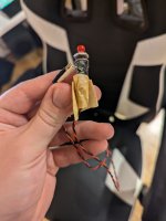
Yes, I've got some 330ohms, some 10kohms, and some buttons - funnily enough, the person who gave this to me also gave me this button:
button.jpg
and said it had been hooked up to it for something! So clearly the previous owner had the same idea. It's a bit old and dirty though, so I'll use my new parts for it - how do I connect it?

@Hugo Holden , thanks for the reassurance! Your picture looks exactly like what I was seeing, so I think it is just keeping those pins high and I'm just seeing a bit of jitter.

I've also managed to verify that the CRT is sort of working, in that I was messing around trying to get a raspberry pi to display something on it, and I did manage to see a dot moving around for a few seconds at a time. I wasn't giving it the right signals, so I couldn't get any finer control than that, but it's nice to know that the electron gun is at least still alive in there!

I think there's probably a bit of wear and tear on the machine - I've started using the 6502's pin 7 as a "sign of life" when I switch it on, to verify that it's got itself into that loop, but now, most of the times I switch it on, I only see a flurry of activity for a couple of milliseconds before pin 7 goes dead. I now have to leave the PET off for a couple of minutes and hope pin 7 will stay alive when I switch it on.

Looking forward to the next thing to try!
 
I'm going to attempt to infer some information based on the above readings and the schematics, just to test my understanding so far.

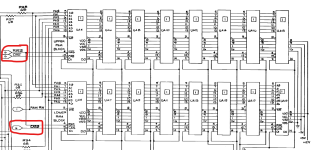
UD1 pin 10 (/RAS0) has activity, UD5 pin 8 (/CAS0) has activity, and UD5 pin 11 (/CAS1) doesn't. According to sheet 5 of the schematics:
1724624556625.png
I can probably infer that the CPU is accessing RAM, but only in the lower RAM block (the lower row of RAM chips in the above image).

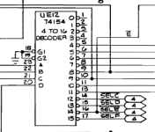
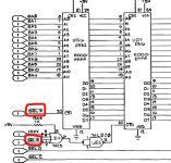
UE12 is a bit weirder. I found it here, in sheet 1 of the schematics:
1724624704253.png
and I'm only seeing activity on pins 16 and 17, so it's only accessing the memory for whatever "SEL E" and "SEL F" point to. Turning to sheet 4:
1724624925948.png
it looks like it's accessing places in the upper chunk of ROM (E000 and above). I think I remember reading somewhere that the operating system is stored in that bit? But I could be totally wrong!

Anyway, this exploring is very fun, and I feel like I'm learning a lot about how the PET works by debugging it!
 
Full marks for your analysis of what is going on. If you were at school I would have given you a gold star!

UE12 pins 16 and 17 toggling away is good. This indicates (as you have already identified) that the CPU is executing instructions from both the KERNAL ROM ($Fxxx) and the EDIT ROM ($Exxx).

The /RAS0 signal has two functions. It goes LOW to refresh the DRAM and it also goes LOW as the first part of a cycle to access the DRAM. If you look carefully at the /RAS0 signal with your oscilloscope, you should observe constant /RAS0 cycles (for the refresh) and then (interspersed between these) will be an extra /RAS0 cycle when the DRAM is accessed.

The /CASn cycle 'completes' the DRAM access - and is only present on the DRAM bank being accessed. A refresh cycle only has a /RAS0 cycle and no /CASn cycle.

If you want to observe the 'double /RAS0' cycle, single shot trigger your oscilloscope on the /CAS0 signal with one channel and observe the /RAS0 signal with a second channel.

Pages 0 and 1 (address range $0000 to $01FF) are very important within a 6502 system, and explains the access to the lower bank of DRAM. Critical system variables and the hardware stack are down here.

Dave
 
Back
Top