I wish I was savvy enough back then to have learned FORTRAN or one of the other programming languages available on the system (when he bought a system, all of the software/manuals/tapes/disks/paper/cards/etc usually came with it). He had compilers for FORTRAN, COBOL and an EASYCODER assembler along with all of the manuals, but dad wasn't familiar with any of them or how to use them. He did teach me some machine language, mostly PDT instructions, and that was enough to get my juices flowing. It wasn't until your simulator that I really understood how the H200 control panel worked since all I had used was the console back then.We used to "sneak" into the computer center in the evenings, to get extra runs of our FORTRAN programs and to explore the manuals and punched-card equipment.
Upcoming Events:
| VCF West | Aug 01 - 02 2025, | CHM, Mountain View, CA |
| VCF Midwest | Sep 13 - 14 2025, | Schaumburg, IL |
| VCF Montreal | Jan 24 - 25, 2026, | RMC Saint Jean, Montreal, Canada |
| VCF SoCal | Feb 14 - 15, 2026, | Hotel Fera, Orange CA |
| VCF Southwest | May 29 - 31, 2026, | Westin Dallas Fort Worth Airport |
| VCF Southeast | June, 2026 | Atlanta, GA |
-
Please review our updated Terms and Rules here
You are using an out of date browser. It may not display this or other websites correctly.
You should upgrade or use an alternative browser.
You should upgrade or use an alternative browser.
Honeywell 200 resurrection
- Thread starter RobS
- Start date
Chuck(G)
25k Member
It's a bit more interesting in that this is Honeywell's own original product, before they bought out the GE operation in Phoenix.
Living near Phoenix, I've often wondered how much mainframe equipment is either buried in a landfill here or in a long forgotten warehouse around here. When I moved here, I scoured several electronics salvage yards but never found anything.It's a bit more interesting in that this is Honeywell's own original product, before they bought out the GE operation in Phoenix.
Chuck(G)
25k Member
A friend joined Honeywell in Phoenix at about the time of the changeover and invited me down for a tour of the plant. I witnessed the engineers working with a direct water-cooled design (apparently algae was a problem and the algacide used tended to corrode the plumbing). Basically, a bunch of racks connected by cables and pipes, all housed neatly in a shell that would probably serve as a VW bug garage. The test console used was a marvel, with nixie bar graph displays, etc. Prowling around the area, I saw various old GE iron tucked away in corners...
RobS
Experienced Member
As I explained in my article in RESURRECTION, the house magazine of the Computer Conservation Society here in the UK, my original reason for conceiving the project was as a way to get rid of a load of obsolete electronics stacked in my garage after my mother-in-law died and we had to move it all out of a shed in her garden in order to sell her home. Disposal of electronic waste in the UK costs money because of regulations about it, so making it into a working device, i.e. an H200, would mean that I could probably give it away for nothing eventually. Of course building the thing is costing more than scrapping the electronics would and I am acquiring even more obsolete electronics in the process so . . . maybe you're right actually.
Regarding IBM groups, my first postings and correspondence were actually with the people involved with the 1401 work at the Computer History Museum in California, i.e. LaFarr Stuart, Ed Thelan, Randy Thelan and Robert Garner. I was setting the record straight about the H200 not being a 1401 clone but a different machine in its own right. Yes, there are just too many people still on the IBM bandwagon.
Our company had a long successful working relationship with Honeywell and their computers until a new manager was brought in who only had experience of IBM technology, so he brought in a crony of his who had managed IBM systems at other companies for him and they scrapped all our highly efficient Honeywell systems lovingly developed entirely in house and substituted IBM technology that was years behind Honeywell's because of IBM's heavy support of their old customer base who were resistant to change. The result was dismal and I refused to work with the antiquated IBM mainframe systems so moved over to PCs using their O/S2, which was very good in comparison. Unfortunately we then switched from O/S2 to Windows on PCs, which was not so advanced and some of my developments simply couldn't run on it at all because I had used the cutting edge features in O/S2 as I do with any system.
They say that nobody ever got sacked for buying IBM but the IT division manager who was brought into our company to make the change from Honeywell to IBM was subsequently politely but firmly asked to resign, which he did, to the great relief of us IT staff. I have never had anything to do with IBM mainframe technology except out of necessity when interfacing with it from O/S2 and I wonder just how much of their reputation was deserved having seen what the BUNCH including Honeywell were achieving at the time. Of course the scene in the UK was different with our own national computer industry being more prevalent. The editor of RESURRECTION only accepted my article for publication because he considered it to be far better written than the usual stuff he got from the academic types working on restoration of our national treasures for our National Museum of Computing at Bletchley Park, which is what our CCS actually does.
I am definitely following my old school's lead in transatlantic relations. They are the only British school whose military style marching band has taken part in your Rose Bowl Parade and I appear to have been the only person to have had an article about resurrection of an American computer published in the CCS house magazine here. If you wonder which flag I choose to salute, it is blue with a picture of the whole world on it because I share a birthday with that organisation and so that flag has been flown on my birthday every year since I was one year old and I used to wonder what it meant. (Sometimes I still do actually looking at the current state of world affairs.) Consequently I regard a small part of Manhattan to be my personal home territory although I'm not sure how I could ever get to it without passing through the USA. Perhaps I could claim diplomatic privilege because of the birthday on my passport, but maybe not.
durgadas311
Veteran Member
I've also seen that same scenario. And it's also been my opinion that IBM does not really lead in technology, but to be fair I think there have been exceptions. Their BlueGene supercomputers had a moment. Their s390 mainframe seems to have a solid following. And their PowerPC processors do have merits. But I've heard time and again, at least back in the 70s, 80s, 90s, that IBM's "new" technology was really 10 years behind what others were producing. But, many people felt more comfortable going with IBM - believing that IBM would move heaven and earth to fix any problem they had. Of course, my view of Honeywell is probably biased as well, just given the nostalgia for that period of time and being my first experience with computers....
They say that nobody ever got sacked for buying IBM but the IT division manager who was brought into our company to make the change from Honeywell to IBM was subsequently politely but firmly asked to resign, which he did, to the great relief of us IT staff. ...
Chuck(G)
25k Member
At the time of the 1401, few bought the 1401; rather, it was more commonly leased from IBM. There were third-party leasing companies who leased older gear. So the saying rings somewhat true...
RobS
Experienced Member
At the time of the 1401, few bought the 1401; rather, it was more commonly leased from IBM. There were third-party leasing companies who leased older gear. So the saying rings somewhat true...
I think the situation in the UK was different from that in the USA because there was not such a large market here, so leasing wasn't so viable. Also British computer manufacturers had a larger share of our market. In fact I am currently arranging with our National Collections Centre access to the ICL archive there because as our primary national computer manufacturer they kept track of other manufacturer's technology, so their archive contains a useful collection of Honeywell manuals among those of many other manufacturers.
Honeywell's stated objective when developing the H200 was to market a machine that could potentially be programmed and operated by clerical staff with little or no previous knowledge of computers. That was why their training and reference documentation was very clearly laid out. Their chief designer emphasised this in a document where he set out the reasons for decisions made during the technical design. The decision to use binary addressing in place of the decimal addressing used in the 1401 went against this principle but was felt to be justified to make the hardware more efficient and hence cost effective.
Here in the UK, where machines needed to be bought rather than leased, companies assigned their most capable staff to programming and operating them to get the maximum return from the large initial capital outlay involved. Therefore, although the real world compatibility of the H200 programming language and architecture made the transition from ordinary office work to programming relatively easy for people like me, we had to push the machine to the limits of its ability quickly in order to prove to our very cautious company directors that further capital expenditure on larger machines in the future would be profitable. Also there were no suitable existing software packages for either the 1401 or H200 that we could buy in to achieve this, so we had to write our own from the very beginning.
I could always find ways to get our first tiny H200 to deliver more than anyone expected, so on the strength of its original success our directors continued to buy bigger Honeywell machines for a long time. That is why I conceived this project, to illustrate that first machine's remarkable versatility. I imagine that leasing machines and buying in ready made software packages from the outset did not put the same initial pressure on a company's computer staff to deliver substantial results so quickly. Both I and the company's assistant manager who had proposed purchase of that H200 to the directors were very grateful that it and the Honeywell field engineer responsible for maintaining it never let us down. I am still corresponding with and consulting that same engineer, who actually installed our H200 back in 1966, while working on this project. The banner page on my website specifically states that the project is a tribute not just to the H200 but also to the people like him who continually maintained its reputation.
Chuck(G)
25k Member
One aspect of the lease-vs-buy decision in the US was US tax law. As a durable good used in business, US Internal Revenue Service (IRS) law specified that a system was required to be depreciated over a fairly long period (10-25 years; I don't recall), with the tax paid incrementally, rather than the purchase be counted as an operating expense in the first year. There were in place regulations how depreciation for a given asset was to be calculation (i.e. straight-line, sum-of-years digits, double-declining balance, etc.).
Lease payments could be treated as an ordinary business expense.
US tax law was and still is a nightmare of regulations, both state and federal, which makes for a wise career choice in accountancy. Since the working life of a computer was far shorter than the depreciation period, it was financially advantageous to lease a system, rather than purchase one. Schools and universities, being non-for-profit enterprises were granted an exemption to this, so purchase was a good option.
It wasn't until sometime in the 80s that the IRS allowed a personal computer purchase to be treated as an ordinary business expense, rather than a punch press or building.
This area of taxation and investment tax credits isn't given a lot of play in historical discussions, which is a shame, as financial decisions are a prime driver of innovation.
RobS
Experienced Member
Schools and universities, being non-for-profit enterprises were granted an exemption to this, so purchase was a good option.
That may explain why I was able to acquire a control panel originally used in a college in Kennesaw Georgia. I think the other one promised to me in California had originally been on a military site there.
When our purchased company H200 here in the UK was scrapped at the end of the 1960s the control panel was very reasonably given to the chap who had pushed the buttons on it for several years. Unfortunately he dumped it when he moved house many years later. The 4K memory module from that machine was given to the assistant manager of the company who had in 1965 taken the initial risk of proposing buying this machine with no proven track record to our board of directors. He acknowledged that it had been my innate programming ability that had contributed substantially to the machine being the success that it was, but I didn't get given any part of it, but I am making up for that now with this project. Programming this machine has never been a challenge for me, but building one is proving to be a more interesting one. When we get to age 80, as I will this year, a good challenge like this one keeps us going I think. At least I sincerely hope it does.
RobS
Experienced Member
It's time to post some pictures, I think.
I have finally managed to install all the major parts of my computer in their new home. Here are some pictures but I will eventually put higher definition ones on my own website.
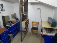
On the left are various provisional power supplies and stacked boxes containing PCBs and other parts. The provisional voltage regulator and current monitoring panel is on the back wall mostly hidden by the two backplanes. On the right is the control panel with the provisional power supply for its lights . . . and more blue boxes. This layout should give me enough space to work on any part of the machine. I haven't connected all the cables yet.
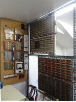
This is a better picture of the regulator panel and the back of the backplanes.
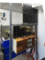
At the front of the backplanes the entire main memory unit is now installed complete with the guide rails for the PCBs. At present I can only operate the main memory for short test periods until I have installed the cooling fans with their housings. Above the main memory are the first few PCBs for the control memory. One of my pending tasks is assembling the rest of these. Although I am currently only installing circuits on the first backplane I have already installed the second backplane above it so that I can use it for temporary test circuits. An advantage of wire-wrapped backplanes with plug in PCBs is that temporary circuits can be built quickly and then stripped out when no longer needed.
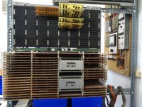
This closer picture of the PCBs shows how essential the guide rails are to keep the boards at the right spacing and allow air from the fans to pass between them from one end to the other. In reality during normal operation the backplanes in a complete machine are mounted inside the cabinet with the PCBs vertical and the fans at the bottom but they are rotated out of the cabinet into the position as above during maintenance, so I will locate the fans on the right hand side. In my design the PCBs that generate the most heat are all on the left side, so at the top when eventually put inside a cabinet . . . some time in the distant future maybe!
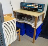
This picture clearly shows the ventilation slots in the PCB guide rails as well as the original H200 control panel now properly mounted on a worktop with its lighting power supply beneath and some of the lights working. Fixed in a corner close to a wall like this the panel would not appear to be in a convenient location for any work to be done on it but . . .
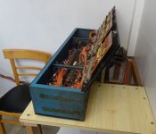
. . . it is actually mounted on a hinged section of the worktop and can be tipped face down to give access to the interior and the cable connectors underneath it. It is heavy and I am getting tired of lugging it about so this arrangement will save me a lot of effort if anything inside it goes wrong in the future.
Having set up the major elements of the machine in a way that enables me to access them easily and connect them all together, I can hopefully now focus what time I can spare for the project onto getting on with the actual electronics side of the work again, which will please my aching back no end. Actually as my wife helped me position the heavier items she will be pleased as well and has now returned to breaking her back doing gardening, her own chosen form of self-torture, our weather and seasons here in the UK no longer conforming to the traditional expectations of gardeners.
I have finally managed to install all the major parts of my computer in their new home. Here are some pictures but I will eventually put higher definition ones on my own website.

On the left are various provisional power supplies and stacked boxes containing PCBs and other parts. The provisional voltage regulator and current monitoring panel is on the back wall mostly hidden by the two backplanes. On the right is the control panel with the provisional power supply for its lights . . . and more blue boxes. This layout should give me enough space to work on any part of the machine. I haven't connected all the cables yet.

This is a better picture of the regulator panel and the back of the backplanes.

At the front of the backplanes the entire main memory unit is now installed complete with the guide rails for the PCBs. At present I can only operate the main memory for short test periods until I have installed the cooling fans with their housings. Above the main memory are the first few PCBs for the control memory. One of my pending tasks is assembling the rest of these. Although I am currently only installing circuits on the first backplane I have already installed the second backplane above it so that I can use it for temporary test circuits. An advantage of wire-wrapped backplanes with plug in PCBs is that temporary circuits can be built quickly and then stripped out when no longer needed.

This closer picture of the PCBs shows how essential the guide rails are to keep the boards at the right spacing and allow air from the fans to pass between them from one end to the other. In reality during normal operation the backplanes in a complete machine are mounted inside the cabinet with the PCBs vertical and the fans at the bottom but they are rotated out of the cabinet into the position as above during maintenance, so I will locate the fans on the right hand side. In my design the PCBs that generate the most heat are all on the left side, so at the top when eventually put inside a cabinet . . . some time in the distant future maybe!

This picture clearly shows the ventilation slots in the PCB guide rails as well as the original H200 control panel now properly mounted on a worktop with its lighting power supply beneath and some of the lights working. Fixed in a corner close to a wall like this the panel would not appear to be in a convenient location for any work to be done on it but . . .

. . . it is actually mounted on a hinged section of the worktop and can be tipped face down to give access to the interior and the cable connectors underneath it. It is heavy and I am getting tired of lugging it about so this arrangement will save me a lot of effort if anything inside it goes wrong in the future.
Having set up the major elements of the machine in a way that enables me to access them easily and connect them all together, I can hopefully now focus what time I can spare for the project onto getting on with the actual electronics side of the work again, which will please my aching back no end. Actually as my wife helped me position the heavier items she will be pleased as well and has now returned to breaking her back doing gardening, her own chosen form of self-torture, our weather and seasons here in the UK no longer conforming to the traditional expectations of gardeners.
Last edited:
RobS
Experienced Member
Here are some more pretty pictures.
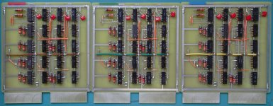
First my custom designed PCM03 logic boards, the PCB's for which I designed and had made five years ago but have only just installed the components on them. They contain 59 original 1960's IC's which implement the address Z register in the H200 along with the address increment/decrement logic. Actually just fifteen are the Z register flip-flops and the other 44 make up the arithmetic logic, but that's primitive 1960's IC logic for you, damned hard work to use. Anyway my design is intended to do the calculation in one clock cycle while the original H200 needed two with its simpler approach.
Next, here's the low tech equipment that I am using to modify original logic boards for other purposes without removing any of the components.
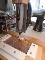
Yes, it really is just a Dremel flexible drive shaft extension mounted on an old sewing machine by means of a home-made vertical slide. The slide is moved by an old bicycle brake lever with its cable attached to the top of the slide pulling against a return spring. The lever is mounted on a wooden stand on the floor so that I can work it with my foot leaving both hands free to position the board on the work table. The single wooden guide rail clamped to the table assists me in positioning the board. The special holder for the logic boards has clamps made of short curtain rail offcuts and a cavity in the thick plywood base to contain the components underneath on the topside of the board. Below is a closer picture of what this primitive setup achieves.
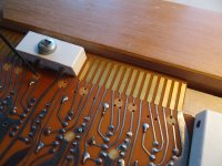
Existing tracks are cut away using a 3mm or 2mm end mill and then 1mm holes are drilled at the cut ends of the tracks for jumper wires on the topside of the board to be attached to form the new wiring. Where extra wires need to be connected to tracks without cutting them I position holes for them adjacent to the tracks as can be seen. This approach produces very accurate results relatively quickly compared to trying to hack at the tracks and boards with hand tools. Given the large number of boards I need to modify it was worthwhile spending a little time putting this contraption together and it has already proved its worth.
First my custom designed PCM03 logic boards, the PCB's for which I designed and had made five years ago but have only just installed the components on them. They contain 59 original 1960's IC's which implement the address Z register in the H200 along with the address increment/decrement logic. Actually just fifteen are the Z register flip-flops and the other 44 make up the arithmetic logic, but that's primitive 1960's IC logic for you, damned hard work to use. Anyway my design is intended to do the calculation in one clock cycle while the original H200 needed two with its simpler approach.

Next, here's the low tech equipment that I am using to modify original logic boards for other purposes without removing any of the components.

Yes, it really is just a Dremel flexible drive shaft extension mounted on an old sewing machine by means of a home-made vertical slide. The slide is moved by an old bicycle brake lever with its cable attached to the top of the slide pulling against a return spring. The lever is mounted on a wooden stand on the floor so that I can work it with my foot leaving both hands free to position the board on the work table. The single wooden guide rail clamped to the table assists me in positioning the board. The special holder for the logic boards has clamps made of short curtain rail offcuts and a cavity in the thick plywood base to contain the components underneath on the topside of the board. Below is a closer picture of what this primitive setup achieves.

Existing tracks are cut away using a 3mm or 2mm end mill and then 1mm holes are drilled at the cut ends of the tracks for jumper wires on the topside of the board to be attached to form the new wiring. Where extra wires need to be connected to tracks without cutting them I position holes for them adjacent to the tracks as can be seen. This approach produces very accurate results relatively quickly compared to trying to hack at the tracks and boards with hand tools. Given the large number of boards I need to modify it was worthwhile spending a little time putting this contraption together and it has already proved its worth.
Last edited:
Nice lab setup you have there Rob! The configuration of the backplanes reminds me of the frames that housed the H3200 CPU and scientific unit that had a pair of backplanes stacked vertically. It should be easy to work on with all of that space around it too.
Kudos on the boards too...very nice! I would never have guessed they were modern PCBs...they look just like the OEM (HEDP) boards.
Kudos on the boards too...very nice! I would never have guessed they were modern PCBs...they look just like the OEM (HEDP) boards.
RobS
Experienced Member
Kudos on the boards too...very nice! I would never have guessed they were modern PCBs...they look just like the OEM (HEDP) boards.
Way back when I was designing the PCM03 boards I also posted THIS ITEM showing how closely I can replicate original boards when the circumstances merit the effort. However, the style of all the boards is primarily dictated by their small size and the limited number of pins on the edge connectors, so in practice the boards will all look similar. Whether intentional close replicas or new designs, all my boards have the mark "H-Pi" on them in the etched copper layer to clearly identify their origin.
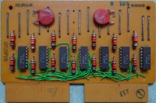
Since posting the pictures of my "Dremel-Singer" milling machine on Sunday I have found in my toolbox a very narrow milling cutter which can cut away a track between adjacent pins on an IC without touching the pins themselves. On the close-up of the board being milled in my previous post it can be seen how the pins for unused input gates on the ICs are connected together and to ground to disable them, but now I have been able to separate these pins with the milling machine in order to use those gates without having to resort to cutting the tracks by hand. Consequently I have now finished modifying the six boards I currently need and can start adding the extra components and wires to reroute the connections on them. That work will complete construction of the control memory output buffer, S register and Y register. Once I have wired up the backplane connections between the boards I can start testing that part of the system, but I plan to build at least part of the control panel interface first.
Here's a picture of the topside of the board being milled in the previous pictures now that it has the new wiring in place. It has been substantially repurposed in a way that using the original edge connector pin connections couldn't achieve but none of the components on the board has had to be moved to do it. The wires may look as though they could have been laid more tidily, but they are interwoven on purpose so that they hold each other close to the board and none sticks out to snag on anything. This saves tacking them down with a glue gun.
Last edited:
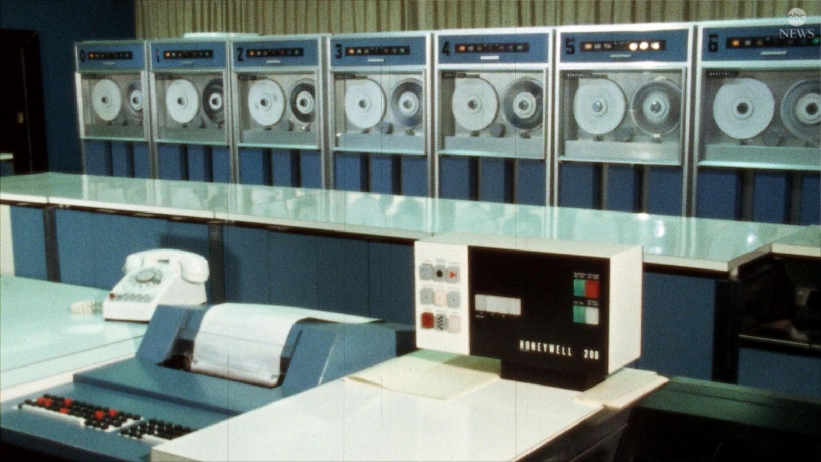
I'm always on the lookout for Honeywell mainframe related stuff, which is probably how I found this project. Yesterday, I found this video clip from the Good Morning America show from July of 2023 that shows an H125 control panel, a tape drive (probably a 204-B8 or 204-B9), and an H200 console with a row of tape drives in motion. The action is only about 10 seconds and begins at the 1:10 mark:
 www.goodmorningamerica.com

Can artificial intelligence pass the Turing Test?
Is AI capable of convincing humans that computers can behave like we do?
RobS
Experienced Member
I'm always on the lookout for Honeywell mainframe related stuff, which is probably how I found this project. Yesterday, I found this video clip from the Good Morning America show from July of 2023 that shows an H125 control panel, . . .
As you mentioned the H125 I should mention that another machine in that range, the H121, appears to have been the only one in the 200 series that was produced during the 1960's with integrated circuit technology as an alternative to the original discrete diode and transistor technology. Honeywell probably chose to do that with the H120 range as they were the physically smallest machines in the 200 series and space saving IC technology would have been appropriate there. I was able to confirm this fact when one of my H200 engineer friends sent me tables of power requirements for various machines in the series. These tables contained information for both the discrete and integrated versions of the H121. The discrete version required large supplies of current on the 15 volt line as the diode transistor logic ran on 15 volts while the integrated version required correspondingly large supplies on the 5 volt line to power the ICs.
I assume that the H121 used the same AA series Honeywell ICs that are in my large collection of logic boards and therefore feel justified in using them in what I intend to be a 1960's style H200. It just happens that Honeywell never produced an integrated version of the H200 themselves but evidently they could have during the latter half of the 1960's if they had wanted to.
I have now assembled a ten foot long cable to carry the 76 signals between my control panel and processor backplane. I had to include some components in the cable connectors to match the panel to my IC logic as the panel was designed to work with the original 15 volt diode transistor logic rather than 5 volt ICs. Also the processor inputs to the panel that work 30 of the lights require a small signal current to be fed into them to light the lights, so wouldn't work directly from standard IC logic outputs that of course sink current. Therefore I adapted a couple of original diode transistor logic boards to act as cable connectors. These actually each contained four inverter circuits with a number of input gates. A similar logic board is shown in the picture below. Note the date in the bottom right hand corner of the board. It shows just how old some of my stock is.
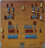
The bottom end of the board contains the input diode arrays. Each input gate has a pull-up resistor connected to the supply line and two diodes, one feeding pull-up current into the output amplifier and the other connected to the input pin. Most of the gates actually have more than one input diode to create AND gates. When an external logic circuit pulls the input to ground the pull-up current diverts from the output amplifier to the external circuit and the amplifier changes state as a result. To meet my control panel's needs I cut the top section off each board leaving just the input diode gates, which I connected to the wires to the panel. With the inputs connected to IC logic on my processor backplane these connectors would feed current to the panel to light the lights when the inputs weren't pulled low by an IC. My design works but . . .
On Thursday afternoon another former Honeywell 200 engineer, an old friend of mine from the 1960's, was coming to see my machine and the control panel in particular. In fact he installed the first computer bought by my employers and programmed by me, an H200, back then and maintained it for many years, which was how we became acquainted. There is a picture of that machine on my website. I had connected the ADDRESS row of buttons on my panel to the address register in my processor so that those buttons would operate as they did originally and the lights would light and stay alight in each button until the CLEAR button was pressed. Naturally the day before he came one of the lights insisted on lighting up even when its button hadn't been pressed, so I had to trace the fault, which turned out to just be a quirk of the input diode gates that I was using.
On the original logic boards the gates rely on the input voltage dropping lower than that feeding into the attached amplifier to deprive the amplifier of all input current. In my circuit the ICs were pulling the inputs to ground but there could still be residual currents leaking into the panel circuits which might be enough to trigger some of the SCRs that drive the lights. Whether a particular gate circuit worked or not depended on which of its diodes had the lower forward voltage drop. In the case of the light that refused to go out the input diode had the higher voltage drop, so it couldn't pull the pull-up voltage low enough for the output diode to stop conducting. The balance was so critical that the fault only occurred once the machine's circuits had warmed up, which had made tracing the fault that much more difficult. The solution was to use a diode with a lower forward voltage drop as the input diode. I couldn't find any old germanium diodes in my stock so instead used the base-emitter junction of an OC72 germanium transistor as a diode to test my diagnosis and this cured the fault as a temporary fix.
My old friend was highly impressed by what I have achieved so far and was ecstatic to be sitting operating an H200 control panel again after having spent so many decades working on those machines and then never even seeing one again for a very long time. The visit clearly brought back many nostalgic memories for him. If you have read the words in the banner at the top of the home page of my website you will know that my project is not just a tribute to the Honeywell 200 but all the people like him who worked to create and maintain its reputation, so I am glad that the visit raised his spirits the way it did.
My permanent solution to the interface problem is to replace all thirty input diodes on the light control lines to the panel with Schottky diodes, which are a more modern and more easily obtained equivalent of germanium diodes or, to be more accurate, point contact diodes in this situation. Each Schottky diode on the input side will pull the voltage down to about 0.45 volts which will fully cut off the PN type silicon diode on the output side which typically has a forward voltage drop of around 0.7 volts.
Of course my concern about compatibility with 1960's technology made me wonder whether Schottky diodes were readily available at that time as I have no examples of Honeywell using them in my collection to confirm that. However, the principle is far older even than the era of the Honeywell 200 as Mr Schottky did his research into metal-semiconductor junctions back when crystal sets with "cat's whiskers" were in fashion, so I think I'm pretty safe and anyway Honeywell could have used germanium diodes to achieve the same result quite easily back in the 1960's. I have read that Schottky diodes were incorporated into the design of the popular 74 series ICs in 1971 but adding metal-semiconductor junctions to IC technology was probably more of a challenge than manufacturing discrete diodes.
Ah, the apparently trivial concerns that beset the conscientious vintage technology replicator!
RobS
Experienced Member
. . . I have read that Schottky diodes were incorporated into the design of the popular 74 series ICs in 1971 but adding metal-semiconductor junctions to IC technology was probably more of a challenge than manufacturing discrete diodes. . . .
Ah, the apparently trivial concerns that beset the conscientious vintage technology replicator!
Come to think of it, all ICs must have metal-semiconductor junctions somewhere to attach the wires . . .
RobS
Experienced Member
It being Sunday I'm off duty from my project today but that doesn't stop me commenting on the less technical side of it. It occurred to me that I know the ideal signature song for this project as it is in the large collection on our home music server. See https://genius.com/Johnny-cash-one-piece-at-a-time-lyrics
Well, I got it one piece at a time and it hardly cost me a dime and I'll have the only one a round. Yes, it's a '65 '66 '67 '68 '69 '70 '71 '72 . . . Honeywell machine. Bless you Johnny, wherever you are up there now.
Well, I got it one piece at a time and it hardly cost me a dime and I'll have the only one a round. Yes, it's a '65 '66 '67 '68 '69 '70 '71 '72 . . . Honeywell machine. Bless you Johnny, wherever you are up there now.
