• Please review our updated Terms and Rules here

Honeywell 200 resurrection

I have an Arduino mounted on a standard H200 PCB that I use as a USB interface between my H200 backplane and my laptop solely to run tests.
Arduinos are very handy! That's a great use for one. I've used them in several projects for my customers. I usually write the initial code for them and they like it because they're familiar with them too and can hack the code as their needs change. The "secret sauce" is in the rest of the board, so it saves me time (and them, money) by using an Arduino.

Thanks for the info about those high wattage resistors...I wondered what they were for too. Given the physical size of the power supplies (as you are WELL aware of!), no wonder even the control panels put out a lot of heat...I can feel it on mine, especially around the status indicators.

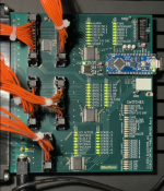
For the switches, I deviated from Honeywell. I'm using internal pullups to 5V that are built into the SPI devices I used. These chips (MCP23S17) can be programmed to generate an interrupt if an input changes, so I don't have to constantly scan the switches with the Arduino Nano Every.

I did keep the idle resistors for the lamps in hopes they will last longer. One thing I did notice is that in a dark room, the CHECK FUNCTION lights glow a little bit. I used an MC33996 to drive them. I didn't wire up the INITIALIZE button the way Honeywell did...I'll let the Arduino handle it (I waffled over that decision for a while).

I think that's great that you joined a maker space! Maybe you'll find some kindred spirits there. We had a TechShop here until they folded several years ago. If your not familiar with them (they had a chain of these shops), they had pretty much everything you would need under one roof to make just about anything: electronics, wood shop, sheet metal, welding, paint booth, etc. That would have been handy for you if you need to recreate any cabinetry or sheet metal parts for your H200. I'm still friends with several people I met there. I'd be willing to bet there will be some there that will be very interested in what you have!! I find the background that you bring to this discussion fascinating!

Whether I am a perfectionist, idealist, realist or masochist remains to be seen.

😅 Maybe one (or more! they aren't necessarily mutually exclusive!), but you're enjoying the journey and that is what matters most! You have many of the pieces (hardware and know-how) to actually pull this off, and that's a start.

If you ever hit an insurmountable brick wall, you could always use something like one of my boards with your control panel (with a bit of rewiring, of course...although you could build an interface that uses the existing wiring and connectors, leaving it pristine) and prod Doug to add a serial interface to his simulator for it. It probably wouldn't be too hard for the sim to communicate with the Arduino for control panel I/O. It would make more sense with your CP given all of the lights and would look very cool (and realistic) while running and much easier to transport to the maker space. It didn't make much sense for mine since it really didn't do much while the machine was running...maybe the addressing mode lights would blink a little, but that's about it (pretty boring). For mine to be more interesting, I would need something to replace the console keyboard and printer. I think a TI Silent 700 would work as it would be easy to interface with and very similar to the Honeywell console in operation. Building a true-to-life Honeywell keyboard and acquiring/restoring/maintaining a TTY print mechanism would be ideal, but probably quite another project.

I'll have to get creative with mine to make it look interesting. The plan is to have several modes using the MODE rotary switch to select a program to run, mainly a lamp/switch test, simulated operation, and random blinkenlights like they would do for a TV show or movie (which I always wanted to do as a kid!). The DISPLAY switch will adjust the lamp intensity (the lamp driver IC has an input that I can drive w/a PWM signal out of the Arduino for intensity), and the FORCE CYCLE switch will change the clock frequency. All three rotary switches use a resistor divider network that go to an ADC input on the Arduino...that saved a bunch of wires. I'll use the ONE CYCLE switch and the EXECUTE BUTTON to allow me to single-step through a program (I think, correct me if I'm wrong, that was the purpose of the ONE CYCLE switch...it sounded logical).
 
Building a true-to-life Honeywell keyboard and acquiring/restoring/maintaining a TTY print mechanism would be ideal, but probably quite another project.

I don't know about TTY print mechanisms but making a realistic Honeywell console keyboard wouldn't be too much of a problem. There appear to be images of one in use two minutes into the title sequence of the film Billion Dollar Brain and it looks like the mechanism is similar to the Honeywell Keytape machine keyboards that I dismantled some years ago. I seem to recollect that the computer's console keyboard had some red keys marked to perform special functions, although I never actually operated our computers back then, and the keyboard in the film has those red keys, so isn't simply a data encoding device keyboard. From the key layout and action I suspect that the key mechanisms were reed switches operated by magnets moved by the keys as on the Keytape machines, the complete switch mechanism for each key being an individual component. I have maybe a hundred of these as well as the slotted metal bars onto which these switches were clamped by their integral plastic clamps to form a complete keyboard assembly. That is enough to assemble the keyboard mechanism so all that would then be needed is suitable keytops. The keytops in the film are flat with smaller round buttons projecting, so the symbols probably weren't two shot mouldings but just printed on plain plastic. The printing wouldn't have worn away because the operator's fingers only touched the projecting buttons. This looks like a typical Honeywell cheap solution through clever design which benefits us people attempting to reproduce such things. If you want to tackle the keyboard project I could dig out what I have for you to make up the mechanism as I have been wondering what use a hundred of these switches could be to me. When I can find the components I'll post a picture of how they fit together.

Later Honeywell visual terminals also had keyboards with magnets in the keys but used digital Hall effect detectors to sense movement of the magnets instead of reed switches.
 
Last edited:
Still used in aerospace. How about this one or here. I suspect that there are also ebay sellers.
Apart from the cost, there's probably more on that 60 USD waxed lacing spool than you'd need. I'd try experimenting with making some from a ball of regular string/twine from a "$2 shop". Melt some candles over a heat source in an aluminium softdrink can cut in half, and draw the twine through it. Reheat and press the treated string between paper towels if there's an excess of wax.
 
You could try using some waxed dental floss. It's nylon, but might work in a pinch. Wear gloves in any case, the stuff is hard on your fingers after awhile. Waxed linen cord is used in many fields, such as bookbinding, jewelry making, basket weaving.... Try your local crafts store--it's not hard to find.
 
I used to become entranced watching the H2040 console typewriter (H220-3) print mechanism. A rectangular block of typefaces would dance around a stationary hammer as it all moved across the platen. Unfortunately, the typing mechanism was not active very much. Yes, that distinctive and colorful keyboard, too. I've thought about trying to write something in java that could replicate the appearance/motion.
 
You could try using some waxed dental floss. It's nylon, but might work in a pinch. Wear gloves in any case, the stuff is hard on your fingers after awhile. Waxed linen cord is used in many fields, such as bookbinding, jewelry making, basket weaving.... Try your local crafts store--it's not hard to find.

I haven't tried using the waxed nylon cord I bought yet but it is made by a European company, SES Sterling, who state that the fibres in it spread out flat to reduce the chance of it cutting into fingers or the insulation on wires as well as ensuring that knots stay tight. That implies that the fibres are not twisted together but simply held together by the wax, unlike ordinary unwaxed cord.

https://www.ses-sterling.com/wp-content/themes/theme_SES/pdf/en/c09_06.pdf
 
Still used in aerospace. How about this one or here. I suspect that there are also ebay sellers.
THX. On eBay the key phrase seems to be "WAXED LINEN LACING CORD"; there are a number of suppliers. Good to know. I wonder as to the significance of cotton vs. flax in an electronics application. Flax fiber is stronger, but I rather doubt critically so. Flax is apparently _more_ hygroscopic, which I wouldn't think to be a good thing ...
 
From the key layout and action I suspect that the key mechanisms were reed switches operated by magnets moved by the keys as on the Keytape machines, the complete switch mechanism for each key being an individual component.

The console keys actually used the same microswitches as the ones used in your control panel, only one per key though instead of two. Each one was wired to one of those large rectangular connectors, if memory serves, and they weren't wired in a matrix like modern keyboards. The wire bundle was an inch in diameter or more. The Keytape keyboards are the plunger style like you said and probably the same as the ones used in their minicomputer lines like Level 6 (although I've never seen one of the mini's keyboards, but I have seen dozens of Keytape keyboards). Back in the early 80s, I scavenged some of the Keytape buttons and made my own numeric keypad for my TRS-80 Model 1 since Radio Shack wanted something like $79 for one and I was just a kid without much money back then.

Mohawk made a keytape that used the same key caps as the Honeywell console but with the plunger switches that the Honeywell keytape used. Here are some photos that I found:
https://deskthority.net/viewtopic.php?t=12471
You can clearly see the mounting rails that you mentioned and they even did a teardown of the switches.

That's the only other machine that I've seen those key caps used on in person, but the photos in the link above show a Burroughs keyboard that used them too. I think I scrapped one or two of those Mohawks back in the day.

Back in the good old days, my dad set up a keytape with a printer (not a 222 but similar in size) for me to play with. I would grab some random tapes from the warehouse and dump them to the printer to see what was on them. I didn't think much about it back then, but it's scary now to think of all of the data that went out the door with the machines when they were sold off for scrap. I recall seeing names and addresses...there were probably account numbers and possibly social security numbers too. Back then, few had the equipment or know-how to get at that data, which would have made it more difficult than it is nowadays to scam. Some people were lucky that I was an honest kid!! 😁

If I had the knowledge back then, it would have been fun to make a microcomputer out of that setup.
 
A rectangular block of typefaces would dance around a stationary hammer as it all moved across the platen.
They did indeed! The ASR 33 type used a cylindrical printhead but the Honeywell consoles used a rectangular one like this from a model 28 TTY: https://kb8ojh.net/station/teletype/images/Hammer_and_Typebox.jpg
There's more here: https://kb8ojh.net/station/teletype/

The print head has 4 rows of 16 characters and is likely the same layout as the model 33 drum but flattened out. There's a series of videos on Youtube where CuriousMarc restores an ASR 33 TTY. I found it interesting because I wanted to know how it worked.

I enjoyed watching the console too. I still remember the sounds and smells of the computer room. I saw my dad's H3200 running OS/2000 (and learned how to boot it and do a vol-prep, "volume preparation", to create a bootable disk in another drive) and the console would come to life every once in a while and print messages for the operator. I still have some notes that I took from back then, but I do recall a startup message and it asking for the time of day. You also had to load a few cards in the card reader at boot time but I don't recall what was on them...probably some configuration info. I remember the operator (he originally worked at Sherwood Medical in St. Louis) that taught me the OS/2000 stuff said that you had to configure the OS during a vol-prep for the type of system and peripherals it was going to run on. He emphasized that you should always tell it that it has more tape and disk drives than what you actually intended to run on because those parameters set a limit for what that disk will allow you use w/respect to the peripherals...you couldn't use more tapes or disks than what it was configured for. I think this was because he had been burned by trying run on a bigger system at some point (maybe their system was upgraded later or they went to run at a backup site) but the OS wouldn't let him use the additional drives.

EDIT: I found a video of a model 28 printing for your viewing pleasure! 😁
Model 28 print mechanism

The model 35 used the same print head too. I don't know which one Honeywell used, but my guess is the 35.
 

Attachments

  • Model 35 TTY.jpg
    Model 35 TTY.jpg
    293.1 KB · Views: 8
Last edited:
I'm guessing the Honeywell consoles used a different print head - they had different characters, and different encodings. I also seem to recall that it looked less "open" - I don't recall the pins being so exposed and the hammer was different. I seem to remember it being a pain because the print head didn't get out of the way, and for doing interactive stuff you often had to roll the paper up to see what had been printed. But it did seem to be less obstructive than the photos of the Teletypes - more "floating".
 
Has anyone else ever noticed the Easter egg when you press the initialize button?

I wonder if that was intentional. :unsure:

H2015 lamp test.jpg
 
Are you talking about the fact that it does a lamp test? I saw that in documentation, somewhere, such that I included it in my simulator.
 
Maybe this will help. :) It's not obvious and I never noticed this until the other day when I turned out the lights in the room:

1710713434993.png
 
It may just be a coincidence. The STOP and RUN buttons would be in the bottom row because they were often used and operators got into the habit of pushing STOP at the same time as INITIALIZE, so INITIALIZE was placed next to STOP to make that easy. INITIALIZE and SYSTEM CLEAR didn't contain lights because they functioned instantly. Moving up, the three address mode buttons were obviously placed side by side regardless of how all the buttons were laid out and they were also used when starting the system up along with those on the bottom row. The top three buttons were just the ones left over and placing SYSTEM CLEAR directly above INITIALIZE made sense and reduced the chance of it being pressed accidentally. Hence the layout was probably dictated more by Honeywell's attention to ergonomics than Easter eggs.

Looking at the six main control buttons in a single row on the H200 style panel, the STOP and INITIALIZE buttons are together on the left with RUN on the right and the other three miscellaneous buttons are in the middle with SYSTEM CLEAR between the other two, so all that has happened on the 2015 panel is that those three, or rather three similar ones, have been moved up to a separate row.

By the way, in the pictures why are the buttons all lit up when the INITIALIZE button isn't being pressed? This only happens on my H200 control panel when I supply it with smooth DC instead of the pulsed DC that turns off the SCRs turned on by the INITIALIZE button. In fact that is how I took photos of my panel with all the lights on previously, by applying smooth DC power and pressing INITIALIZE momentarily to trigger the SCRs, but it isn't what the panel is meant to do. The lamp test should end as soon as the button is released.
 
Last edited:
It probably is a coincidence, but I think it's a happy one. :)

All of the switches and lights for my project are individually controlled by an Arduino Nano Every. I start a project such as this by writing some test code to make sure everything works before I dive into the meaty code. So far I've only written the code to test out the lights and the code that's running for this photo just blinks all of the lights on/off a few times and then cycles through each one individually. Now that I know that's working, I'll code up the drivers for the switches. One of the meaty routines will work as you'd expect of a real H2015, at least as best as I can recall, and the INITIALIZE button will light everything up as it should. One liberty I took was to add lights to the ALT N and DISPLAY CYCLE COUNTER buttons...those weren't originally there. I did leave them out for the INITIALIZE and SYSTEM CLEAR buttons.
 

Attachments

  • 1710805195151.png
    1710805195151.png
    952.8 KB · Views: 2
I enjoyed watching the console too. I still remember the sounds and smells of the computer room. I saw my dad's H3200 running OS/2000 (and learned how to boot it and do a vol-prep, "volume preparation", to create a bootable disk in another drive) and the console would come to life every once in a while and print messages for the operator.

How old were you then? I recall the console on one of our later machines developing an embarrassing fault. Given what has already been written here about the console printer mechanisms I don't know why one particular print position would stop printing but it did on our console. One of the frequent operator messages gave the block count from tapes as they were loaded, so the words "Block count" appeared all the way down the console log. Unfortunately the printing fault persistently omitted the second "o" in this text . . . Yes, that was very unfortunate.

Having been programming our company's H200 and subsequent machines from 1966 onwards I very much feel my age when someone mentions their dad working on an H3200. In contrast my uncle died somewhere in the trenches in France early in World War One. I have never formally studied or worked in electronics but have been playing with it as a hobby for seventy years now. I guess some people would consider designing and building a replica H200 to be a bit more than playing, but my project is just that as it doesn't matter too much to me whether ultimately my circuits work or not but rather how well I cope with the problems I face along the way.

If you can meet with triumph and disaster
And treat those two impostors just the same;
(If . . . by Rudyard Kipling . . . of course . . . but then I'm English.)
 
I was in high school when I was introduced to our Honeywell 2040, early-mid 1970s. So, a "kid" by most definitions but definitely "not my dad's computer". We used to "sneak" into the computer center in the evenings, to get extra runs of our FORTRAN programs and to explore the manuals and punched-card equipment. They ran OS/2000, so the console was not only interesting to watch for the mechanical fascination, but also to try and figure out what OS/2000 was doing and telling the operator. I recall (unless memory fails) that messages from a job were prefixed with a unique letter, and that the same letter was used as a prompt when entering something into that job. and there was some operation to get the attention of OS/2000 (pressing a button, probably the INTERRUPT one) so you could type commands or job input.
 
How old were you then?
I was around 13 at the time and just beginning to get more serious about computers. I bought a TRS-80 around '81 and taught myself BASIC and some Z80 assembler.

That's a great/hilarious story about the missing "o"! :D

As far as building your replica, it sounds like it's the challenge that draws you into it and solving the problems along the way. I've always enjoyed fixing things since I was very, very young and I still do. At least now I get paid for it! :D I think that using our brains to solve problems helps to keep us young, so keep at it!

The H200/2000 series are quite old now and certainly don't enjoy the popularity that the IBM systems of the day enjoy, so we are in a small/exclusive club by comparison. Occasionally, and it happened this morning, someone will mention Honeywell on one of the mainframe groups on Facebook (Mainframers in this case, but sometimes in Vintage Mainframe Enthusiasts too). I haven't seen a group exclusively for Honeywell, but they do exist for IBM and others.
 
Back
Top