• Please review our updated Terms and Rules here

ITT Satellite navigation system 6000 (PDP8/L)

Had a recap reading my restoration blog, seams like I never used the 2N3725. I intended to use them as replacements for the DEC1008's on the G221 boards. I found the 2N3444 transistor, it's a perfect replacement for DEC1008 (MM1008). I don't have any of those left.
 
In the meanwhile I had some contact with Vince about the flip chip tester.
From the first moment that I got it running I started testing the boards.

The first cards which I tested were a few spare ones. The tester
works so now it was time for the real work.
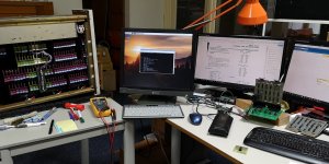
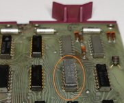
PDP8L - 44.jpg

The first card in my 8L was the M220 to test. If passed the tests with flying colours!
The second M220 > defect
The third M220 > defect
The fourth M220 > defect

So I began to wonder if I had damaged the tester. So I put in the first card again,
and it worked. So those other cards were really defective. That was just a bad start
and I began to worry if there would be a huge amount of TTL chips being defective
in the rest of the machine. Fortunately that was not the case...

The flip chip tester in combination with a HP logic comparator is a very powerful tool!
In the more complex boards you will find faulty chips in no-time.

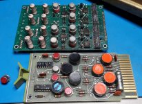
Not all boards can be tested on the tester. Analog boards and boards with
busload resistors can't be tested. But you can test these very easy by hand.

Besides defective TTL chips I had to replace a huge amount of diodes.
Due rust the glass of some diodes was breaking. The result was a lot of
shorted or OC diodes.
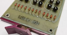
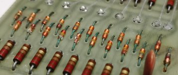
PDP8L - 45.jpg PDP8L - 46.jpg

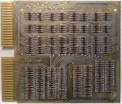
This was also the case in the core stack. I've tested these diodes with
a Hameg HZ65 component tester. This tester is capable of pushing 250mA
RMS trough the component. While testing there were diodes which showed
a little leakage current. And after a few seconds you just saw them break down.
I know the Hameg HZ65 is also vintage and quite rare. But it is very simple to build.

I've kept a history from the defective boards and that I've done to repair them.

A04 M220 1x 7440
C08 M216 1x 7474
C13 M117 2x 7420 defective all 3 replaced
D27 M623 12x diode
C27 M623 12x diode
D27 M623 12x diode
C30 M660 2x 7401 1x 3009 replaced by BC547
D29 M906 40x diode
D30 M906 40x diode
C03 M700 1x diode
D18 G221 11x diode
D19 G221 11x diode 1x 7400
C18 G221 11x diode
C19 G221 11x diode
D24 G221 11x diode
D23 G221 11x diode (*)
C23 G221 11x diode (*)
C24 G221 11x diode (*)
B23 G228 1x 7440
C25 G228 1x diode (*)
D25 G228 2x 7440
A03 M220 1x 7460
A04 M220 1x 7453
A05 M220 1x 7460 1(2)x 7453
C32 M706 1x 7440, 3x 7474, 2x 7400 (1968 board not original from this machine)
Core stack 40x diode

Total replaced components for now:

22x TTL IC
1x transistor
246x diode

I can put data into core now but it gets a bit corrupted. It seems the core voltage
is 6 volts too low. I think this is a fault in the regulator board. Does anyone have
the guideline to correctly set the memory voltage and timing?

Regards, Roland

(There is one board left for the flip chip tester in case anyone is interested)
 
The flip chip tester in combination with a HP logic comparator is a very powerful tool!
In the more complex boards you will find faulty chips in no-time.
Can confirm. It's a great tool however you are limited by how many of the reference chip jigs you got. Has anyone ever made replicas?
 
Can confirm. It's a great tool however you are limited by how many of the reference chip jigs you got. Has anyone ever made replicas?

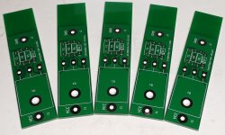
Yes I did! There are gerber files online free to download. The text on the PCB was only for the 16 pin
but if you have an original card (or card numbering on paper) you dan just drill the holes for the 14 pin.

And remember, you don't need a PCB for each single chip!
You only need a match for the outputs and power pins of a chip.

So I have one board for the:
SP380 / SP384
7400 / 7486 / 7437
7410 / 7411 / 7427
7420 / 7440 / 7450
7404 / 7405 / 7406 / 7407 / 7417
etc...

Just put a socket on that board and put the right chip in which you need to test.

Regards, Roland
 
So I got a bit further...

I've got my crowbar PCBs so I will build and test these soon.
PDP8L - 47.jpg

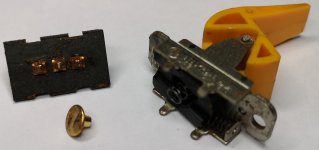
The deposit switch was giving problems. There was some dried out grease in it.
After cleaning the switch worked fine.
PDP8L - 48.jpg


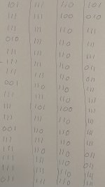
After toggeling in all zeros into memory I got zeros back.
But after entering ones I got this back. Al lot of corrupt data.
You can see that bit 8 never goes to a one.
PDP8L - 49.jpg

That defective bit 8 was caused by a defective DEC1008.
I didn't have these but I got some old boards here with the BFY56 on it.
This transistor seems to be fast enough and fixed bit 8.
PDP8L - 50.jpg

But I still got random errors. So I raised the memory voltage to 27V.
That gave a much better result. But after running a while the memory
still gets corrupt. Here you can see what happens.


Still not bad after replacing 22 TTL chips, 246 diodes and two transistors ;-)
So to be continued...


Regards, Roland
 
Your repairs look very similar to what was needed for the RICM's PDP-8/L. We replaced less diodes, and more SN7474 ICs.

With the SN7453 and SN7460 parts it can be difficult to determine which one of them is causing the problem. In many cases we just guessed and replaced one. If it didn't fix it we replaced the other.

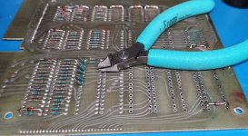
We had some bad diodes on the core stack. We replaced them with 1N4149 diodes. We cut the leads next to the glass part of the diode, bent the leads perpendicular to the PCB, put the new diode in place, wrapped the leads of the new diode once around the old leads, soldered the leads, and trimmed the old and new leads.

We ended up with the memory voltage set to 23.29V, so your 27V sounds a little high.
Have you checked the timing for the STROBE FIELD 0 signal?
 
With the SN7453 and SN7460 parts it can be difficult to determine which one of them is causing the problem. In many cases we just guessed and replaced one. If it didn't fix it we replaced the other.

This is what I have done with the 7460, I could at least find one defective one in this way.
Just pressed a good chip on top of it. The PCB did pass his tests so the 7460 underneath was broken.
This does not always work off course but it can help finding faults with open collector devices.

PDP8L - 51.jpg

But I had to use the guess method at another board as well for a broken 7460...

We ended up with the memory voltage set to 23.29V, so your 27V sounds a little high. Have you checked the timing for the STROBE FIELD 0 signal?

Yes it is quite high, that was why I asked in an earlier posting for the memory alignments.
But I found these in the meanwhile...

I would have started with the memory timing.

Yes, that is what I'm going to do next.
 
Have you checked the timing for the STROBE FIELD 0 signal?

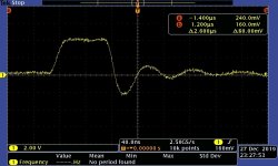
Checked it, but the STROBE FIELD 0 signal didn't look bad to me. (Don't mind the
ringing on the cables) I think it is good idea to check all the timing in the machine...
PDP8L - 52.jpg

But the memory problem was getting worse and worse. Like something was
pulling the memory power lower and lower behind the current limiting resistors.
When I pulled D25 ( G228 ) the results in memory got much better for the parts
that were working. Checked the board and swapped it for another. But putting
back that G228 or another one just makes the problem worse again.

I didn't trust this behaviour, so I checked the core stack diodes again. Guess what...
Another 32 diodes broke down...! Most of them short circuiting...
These things are really horrible in this machine. :?
 
I had to change many diodes and they broke down after a while. So the memory broke down over and over again.

One interesting thing was that I only had to change diodes on one of the diode boards. When I measured the forward diode drop voltage it differed between the boards so I guess that the boards where populated with different diode models or diodes for different batches.
 
I had to change many diodes and they broke down after a while. So the memory broke down over and over again.

That is the reason why I replaced all the diodes on the other boards if I
found several defective ones on a single board.

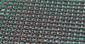
I guess I was a bit naive to think that the core stack would be different. There are now more
than 70 defective diodes of the 512 total on the stack. In the first place I replaced only
the broken ones... But I should have replaced them all in the first place.

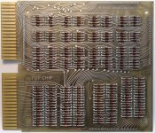
So I did a bit of soldering today. The G611 has 256 brand new diodes on it now :D
I've ordered some more diodes to do the other board as well... Maybe a bit crude...
But I don't like to reopen the system once in a week if another diode breaks down again...

PDP8L - 53.jpg

One interesting thing was that I only had to change diodes on one of the diode boards.
When I measured the forward diode drop voltage it differed between the boards so I guess that the
boards where populated with different diode models or diodes for different batches.

Interesting, it could also be a different brand. Some diodes
on other boards in my system don't have problems. Unfortunately the
diodes on my core stack are just as bad as the most others in the system.

To be continued...
 
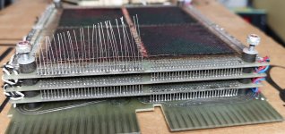
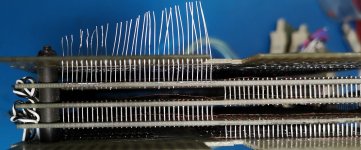
Happy new year! :D I've replaced all 512 diodes on the core stack, 256 diodes on both sides.
The replaced diode counter is now on 718... Checked all X, Y, sense and inhibit wires.
No problems here and memory runs flawless on 22.5V now!

PDP8L - 54.jpg PDP8L - 53.jpg PDP8L - 55.jpg PDP8L - 56.jpg PDP8L - 57.jpg PDP8L - 58.jpg

Besides that, it looks much better then when I got it... Yuk...
PDP8L - 41.jpg

After a while when I was testing the repaired stack I stumbled into a constantly set bit again.
It turned out to be a repaired G228 was broken again. A brand new Signetics 7440 which I
had placed on it broke down. And guess what, 10 minutes later the other Signetics 7440 on it
broke down as well... Both date from early 1974. Probably the G228 is pushing the 7440 to its max...
Apparently never used old chips, even stored properly in all those years, can let you down...

Memory seems to run fine now and I can debug the rest of the machine. It seems some
accumulator operations fail. For example the CML, RAR and some others are clearing the whole AC.
So I think there is something about bit 4 making troubles here.

But I think I'm first going to check the other boards which I had put a new 7440 on. :-| You never know...
 
Roland,
Great work so far, what a project but there is good progress.

As for the broken 7440's.
Try to find out the amount of inputs they have to in comparison to the datasheet.
Maybe it is running on its edges.
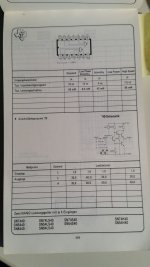
Here a TexasInstrument type 7440 (pocket Guide 1979)

TexasInstruments-7440-data.jpg
 
For example the CML, RAR and some others are clearing the whole AC.
Oops, my mistake! I was single stepping trough the program with the start knob.
But you need to use the start knob just once and then continue with the cont knob.
-feel a bit stupid- I guess it was a bit late :crazy:

I've done some instruction tests with my PDP8/L and I realised a bit late that
a command like BSW (ByteSWap) was not supported yet in the PDP8/L.
That one came with the PDP8/E.

I used these tests

Program 20: Group 1 Microinstruction test omitting the BWS instruction. Passed!
Program 21: Group 2 Microinstruction. Passed!
Program 24: JMS instruction test. Passed!
Program 25: JMP instruction test. Passed!
Program 26: Visible AC increment. Passed, runs for hours now without any problems!
Program 27, 30: Both checkerboard programs. seem to run fine.

Program 20:
ISZ instructions do not pass the test. I've compared it with the behaviour on my 8/M
and it is a bit different. Does anyone know if there are some more instructions not being
supported on the PDP8/L which were introduced later on the 8/E systems?
Or can anyone confirm the outcome of that program on a PDP8/L for me?

Regards, Roland
 
Last edited:
In small computer handbook pdp/8e there is a table with differences to the pdp8/e and it's predecessors. Table 2.1 page 2-10.
 
In small computer handbook pdp/8e there is a
table with differences to the pdp8/e and it's predecessors. Table 2.1 page 2-10.
Thanks. Checked it, but that is the instruction how to operate the PDP8/E.
(Or I have a different version of the book?)

What I'm searching for are differences in the supported instruction set between the PDP8/E and PDP8/L.
Just like BSW which is a byte swap on a PDP8/E and just a no-operation in the PDP8/L.
The BSW command just does not exist on the PDP8/L.

I was wondering if there is a cross list of supported instructions which the machine can do.

Regards, Roland
 
I wrote a paper comparing all of the 8 CPU's a while back. The note says 2010 but I started working on it in the 90's. I'll attach it here. Let me know if you see any mistakes.
 

Attachments

  • PDP8-comparisons.txt
    28.8 KB · Views: 3
Back
Top