Well, that's embarrassing! My speculation about the different Turboroms was nonsense. I discovered that the floppy drive in my Kaypro 10 had its drive select jumper set to ds2 instead of ds1. No wonder it wasn't showing up. I discovered this when I used Turbomap to reveal the drives and their settings. Should have checked the computer more carefully when I got it from Ebay. In any event I now have two hard drives of 40 meg each split into 6 partitions. This is an enormous amount of storage space for a CP/M machine. And I still have a 60k TPA. Now to fill them up!
- VCF South West - June 14 - 16, Davidson-Gundy Alumni Center at University of Texas at Dallas
- VCF West - Aug 2 - 3, Computer History Museum, Mountain View, CA
- VCF Midwest - Sept 7 - 8 2024, Schaumburg, IL
- VCF SoCal - Mid February 2025, Location TBD, Southern CA
- VCF East - April 2025, Infoage Museum, Wall NJ
-
Please review our updated Terms and Rules here
You are using an out of date browser. It may not display this or other websites correctly.
You should upgrade or use an alternative browser.
You should upgrade or use an alternative browser.
KAYPRO and KayFreHD as a hard disk module
- Thread starter Frank S
- Start date
Sharkonwheels
Veteran Member
I can tell you from experience, and '84 TurboROM is an '84 TurboROM. Make sure you are using v3.4.
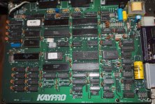
From your pics, you definitely have an '84 board, which is identified by the RAM being in front left corner, and the interfaces being on the right (viewed rom the front) edge of the board.
The big empty area at the right rear is for a transformer, front right area is for the clock battery, plus empty space in both areas for respective support TTL chips.
This is what an '83 K10 mainboard looks like (already with a z80 piggyback for the Advent RAMDisk, and a non-pictured Advent "personality decoder"):

This is what an '84 K10 Mainboard (fully loaded with clock/modem, but battery removed for now to prevent leakage) sometimes referred to as an "MTC board":

As to the KAYPlus ROM, some additional insight, as Gene mentioned, might be necessary...
The KAYPlus code is looking for an older converter board, which was in the original batch of K10s, but were later replaced by Kaypro under warranty.
They reversed the reset line, hence when the KAYPlus encounters the newer board, it may be having the same effect on the FreHD: Keeping the reset signal tied up.
I know that is an issue in getting the K10 working with the KayPlus ROM, with the 2nd rev board and the WD1002 board to an MFM drive. Been there, done that, fought that battle and lost.
Someone would need to replicate the original board.
Frank / Jaquinn: Can you guys check the logic using the Kayplus ROM with the interface attached? I'll try to find the necessary info on the 1st rev adapter board.
From all I have read/Heard/Seen, the KayPlus ROM is in many ways superior to the TurboROM, however the hardware issue is a showstopper.
From your pics, you definitely have an '84 board, which is identified by the RAM being in front left corner, and the interfaces being on the right (viewed rom the front) edge of the board.
The big empty area at the right rear is for a transformer, front right area is for the clock battery, plus empty space in both areas for respective support TTL chips.
This is what an '83 K10 mainboard looks like (already with a z80 piggyback for the Advent RAMDisk, and a non-pictured Advent "personality decoder"):
This is what an '84 K10 Mainboard (fully loaded with clock/modem, but battery removed for now to prevent leakage) sometimes referred to as an "MTC board":
As to the KAYPlus ROM, some additional insight, as Gene mentioned, might be necessary...
The KAYPlus code is looking for an older converter board, which was in the original batch of K10s, but were later replaced by Kaypro under warranty.
They reversed the reset line, hence when the KAYPlus encounters the newer board, it may be having the same effect on the FreHD: Keeping the reset signal tied up.
I know that is an issue in getting the K10 working with the KayPlus ROM, with the 2nd rev board and the WD1002 board to an MFM drive. Been there, done that, fought that battle and lost.
Someone would need to replicate the original board.
Frank / Jaquinn: Can you guys check the logic using the Kayplus ROM with the interface attached? I'll try to find the necessary info on the 1st rev adapter board.
From all I have read/Heard/Seen, the KayPlus ROM is in many ways superior to the TurboROM, however the hardware issue is a showstopper.
Sharkonwheels
Veteran Member
Found the explanation of the small circuit board in early and later Kaypros (TurboROM v3.4 Manual, appendix H, page H-4):
H.3. Early Kaypro 10 Upgrade 81-303, Explanation
The two versions of the small circuit board differ primarily in
how they generate the master reset signal for the hard disk
controller board. The early version connected the second floppy
disk drive select signal directly to the hard disk controller
master reset. The later version of the small circuit board uses
the inverted second floppy disk drive select line for connection
to the hard disk controller master reset.
The modification to the early version of the small circuit board
detailed in this appendix inserts an inverter into the master
reset logic for the hard disk controller. The addition of the
inverter makes the early board functionally equivalent to the
later version.
Note: The original Kaypro utilities PUTSYS.COM, PUTOVL.COM
and FMT305.COM, which were provided with the computer
should not be used after these modifications. If you
are inserting the Kaypro 81-302 ROM, replace these system
utilities with versions from a later model Kaypro 10. If
you are inserting the TurboROM, the utilities
TURBOGEN.COM and K10FMT.COM, provided on the TurboROM
Support Software Diskette, should be used.
The actual modification of the early board (TurboROM v3.4 Manual, Appendix H, page H-3):
5. Modify the Small Circuit Board
Make the following changes to the small circuit board.
Keep the wiring short and as neat as possible. The set
of 50 pins will be referred to as J1; the set of 40 pins will
be referred to as J2. On the solder side of the circuit
board, a square solder pad identifies pin 1 of each set of
pins. All pins in the row with pin 1 are the odd numbered
pins, all pins in the other row are even numbered pins. Refer
to Appendix E for basic information concerning the pin
numbering of IC's. Wires should be installed on the solder
side of the circuit board.
1. Cut the trace that runs from J1 pin 45 to J2 pin 39.
2. Cut the trace that runs from U1 pin 7 to U1 pin 2.
3. Add a wire from U1 pin 1 to J1 pin 45.
4. Add a wire from U1 pin 3 to J2 pin 39.
5. Add a wire from U1 pin 2 to U1 pin 14.
Ref: Plu-Perfect Systems Advent TurboROM V3.4 Manual (text version: ftp://ftp.mrynet.com/operatingsystems/Kaypro/Private-Images/TROM-DOC/Turbo_Rom.txt )
From what a few of us here gathered, it looks like the KayPlus is looking for the early mid-board, and not the later one. It never releases the reset on the WD1002.
Also, historically speaking, the way we've adapted the 27(c)64 EPROMs to work in the K10/83 with 24-pin socket, was to tie pins 26,27,28,and 1 together, and then jumper from P2 on the 2764 to p2 on the Z80.
rosaage
Experienced Member
I got 3 frehd to kaypro adapter boards from oshpark in the mail today. If anyone wants a board I can sell the two extra.
Price + international priority shipping would be around 7 usd per board. PM me if you are interested.
Price + international priority shipping would be around 7 usd per board. PM me if you are interested.
dmemphis
Experienced Member
I have read the whole thread. I'm having trouble piecing together precisely what I need to
get a older version model 10 (HD connector in the middle of the board) running with a FReHD.
I'm not so interested in Advent and KayPLUS roms, which everyone else seems to be- which
I think is complicating the install for me. I gather I may not need to do anything with the ROMS
in this case... or are those enhanced ROMS actually needed to handle the FReHD correctly?
ie: sector sizes?
mikerm
Experienced Member
Huge thanks to geneb for getting me a floppy drive for my 2x, it's now booting again!
It's been so long now since I started this project I have completely forgotten everything.
My 2x has that same K10 board as posted earler and now an Advent ROM (also thanks to geneb), so now I get to re-learn what all I need to do next.
cellarcat: I LOVE the female header idea, I guess I have to get to ordering a 50pin female header, that's a lot better than my 2 short scsi ribbon cables.
Last edited:
mikerm
Experienced Member
Ok, I guess I need some more help from some kind soul.
I have kinda made progress, sorta.
According to sharkonwheels and the pictures he posted earlier, I apparently have a 84 K10 (MTC) board in my 2X. My board assembly sticker reads 81-809. I have the Advent Turbo ROM (3.4) installed. I am using the "geneb board" on the side header, which I soldered in myself. I toned out all the pins to make sure they are making contact.
I ended up doing what cellarcat did and put a female header on the board, it's so much nicer than messing with 2 cables.
Anyway. So when I flip on the Kaypro the green LED flashes for a second, which I'm assuming from YT videos and such that's normal. Then when I use Advant's tool to format an HDD, I'm not entirely sure what all to put in for a custom drive, or what other drive to use. I can't find anything anywhere on that, and I'm not sure how anyone else did it because those details seem to be missing from everywhere (unless I'm really that blind). The documentation that came with the FreHD lists the Cylinders and Heads for the TRS-80 images, but not the different CP/M images.
Basically I'm guessing I need to know for ADVFMT.COM:
Cylinders
Heads
Starting cylinder for precomp (default 0)
Buffered Seek Y/N (If yes, drive step rate in milliseconds x.x)
Sector Skew (default 1)
When I try something, anything it flashes the green LED for a split second, then the red LED comes on for 5 seconds or so. The error I get is "compare error". After the red LED goes out the green one then flashes for a split second.
Any ideas anyone?
Edit: I noticed in the Advent notes above there is supposed to be a K10FMT.COM on the disk which mine didn't have for some reason. I added it and while I don't need all that information, and it very quickly goes through and "formats" it, the FreHD does nothing at all. Very weird.
Last edited:
I have a 2X with the fully-populated board and have just ordered boards from OSH Park. I also need to get another FreHD.
I think the female headers on the adapter board will make things cleaner.
Is the only difference between the 2X and 4/84 the ROMs and software?
I think the female headers on the adapter board will make things cleaner.
Is the only difference between the 2X and 4/84 the ROMs and software?
jbemond
Member
If you read this page http://www.quicktrip.co.nz/jaqblog/home/94-kprofrehd3 you will see that there is also another version of the GAL equation
. I also have several Kaypro II and II and I would like to install FreHD :DTo access the full 8K I needed to connect U60 pin 13 (in addition to Pins 14 and 15) to the GAL and make a small change to the equations to generate the /OE signal for the larger ROM.
My new FreHD boards arrived. I updated one to 2.14 and built one of geneb's adapters. The system is a Kaypro 2X with the later universal board. It has the KayPlus ROM installed already so I gave it a try.
I copied the cpm image to hard4-0 through hard4-3 so I didn't have to guess which one was correct. The idea I had was to get it working then check each of the images to see which one was actually used.
in the HDCNFG program I tried 15MB first and it failed verify on cylinder 0 head 6 (and the FreHD locks up when the program tries to reformat). I then tried 5MB and it got up to cylinder 3 before the verify failed and the FreHD hung.
Is this one of the previously-mentioned issues with the KayPlus ROM or am I doing something wrong?
Will an actualy Kaypro 10 ROM work or should I try an Advent TurboROM? Does anyone have a link to the disk images for the TurboROM?
Switching to a Kaypro 10 ROM worked and I have two 5MB partitions. I want to try with the TurboROM.
One thing I noticed is when restoring from the Kaypro 10 disks I had several errors on disk 8 due to missing files. I'm using the k10hald.zip images. Is that normal?
One thing I noticed is when restoring from the Kaypro 10 disks I had several errors on disk 8 due to missing files. I'm using the k10hald.zip images. Is that normal?
ldkraemer
Veteran Member
Eric,
I've got this Directory listing of Disk #8 in the ZIP file I have. Does yours match this? Or do you have a list of the missing files?
User 9:
Name Bytes Recs Attr update create
------------ ------ ------ ---- ----------------- -----------------
TEACH6U .CMD 2K 12
TEACH7 .CMD 8K 60
TEACH7P .CMD 6K 44
TEACH8 .CMD 8K 56
TEACH8F .CMD 6K 40
TEACH8R .CMD 2K 16
TEACH9 .CMD 8K 60
TEACHC .CMD 2K 12
TEACHI .CMD 8K 64
TEACHXC .CMD 2K 8
TUTMEM .MEM 2K 8
TUTNABK .DBF 2K 12
WHITEHSE.CMD 2K 16
User 10:
Name Bytes Recs Attr update create
------------ ------ ------ ---- ----------------- -----------------
CB-BANK .DBF 2K 8
CB-BOOK .MEM 2K 4
CB-CANCL.CMD 4K 20
CB-CHECK.CMD 8K 54
CB-CHECK.DBF 2K 8
CB-CLEAR.CMD 4K 19
CB-DATE .CMD 2K 14
CB-DEPST.CMD 10K 77
CB-DEPST.DBF 2K 8
CB-HELP .CMD 4K 24
CB-MAIN .CMD 4K 25
CB-MASK .CMD 2K 10
CB-NBWD .CMD 6K 39
CB-RECON.CMD 8K 58
CB-REPRT.CMD 12K 89
DBASEMSG.TXT 50K 392
DGEN .CMD 4K 18
DGEN .OVL 8K 52
DSORT .COM 12K 93
FILEGEN .CMD 20K 157
FORMGEN .CMD 10K 79
IN-ADD .CMD 4K 19
IN-CHNG .CMD 2K 13
IN-CLEAN.CMD 2K 9
IN-DATE .CMD 2K 8
IN-DELTE.CMD 2K 4
IN-DTAIL.CMD 2K 11
IN-HELP .CMD 4K 18
IN-INIT .CMD 2K 5
IN-MAIN .CMD 4K 18
IN-MAIN .DBF 2K 8
IN-PDESC.NDX 2K 16
IN-PNUM .NDX 2K 8
IN-REODR.CMD 2K 9
IN-RPT .CMD 2K 8
IN-RPT1 .FRM 2K 2
IN-RPT2 .FRM 2K 4
IN-UPDTE.CMD 4K 28
IN-VIEW .CMD 4K 27
IN-VWED .CMD 2K 13
INSTALL .COM 14K 112
LABELGEN.CMD 4K 29
LB-NAMES.DBF 2K 8
LB-PRINT.CMD 4K 28
MENUGEN .CMD 6K 38
REV-OFF .CMD 2K 4
REV-ON .CMD 2K 4
ZIPIN .COM 30K 235
ZSCRN .OVL 20K 159
User 15:
Name Bytes Recs Attr update create
------------ ------ ------ ---- ----------------- -----------------
RELOAD .8 2K 1
63 Files occupying 366K, 32K Free.
Floppy 8 SUB file:
Thanks.
Larry
I've got this Directory listing of Disk #8 in the ZIP file I have. Does yours match this? Or do you have a list of the missing files?
Code:
cpmls -f kay2 -D K10HALD8.RAWUser 9:
Name Bytes Recs Attr update create
------------ ------ ------ ---- ----------------- -----------------
TEACH6U .CMD 2K 12
TEACH7 .CMD 8K 60
TEACH7P .CMD 6K 44
TEACH8 .CMD 8K 56
TEACH8F .CMD 6K 40
TEACH8R .CMD 2K 16
TEACH9 .CMD 8K 60
TEACHC .CMD 2K 12
TEACHI .CMD 8K 64
TEACHXC .CMD 2K 8
TUTMEM .MEM 2K 8
TUTNABK .DBF 2K 12
WHITEHSE.CMD 2K 16
User 10:
Name Bytes Recs Attr update create
------------ ------ ------ ---- ----------------- -----------------
CB-BANK .DBF 2K 8
CB-BOOK .MEM 2K 4
CB-CANCL.CMD 4K 20
CB-CHECK.CMD 8K 54
CB-CHECK.DBF 2K 8
CB-CLEAR.CMD 4K 19
CB-DATE .CMD 2K 14
CB-DEPST.CMD 10K 77
CB-DEPST.DBF 2K 8
CB-HELP .CMD 4K 24
CB-MAIN .CMD 4K 25
CB-MASK .CMD 2K 10
CB-NBWD .CMD 6K 39
CB-RECON.CMD 8K 58
CB-REPRT.CMD 12K 89
DBASEMSG.TXT 50K 392
DGEN .CMD 4K 18
DGEN .OVL 8K 52
DSORT .COM 12K 93
FILEGEN .CMD 20K 157
FORMGEN .CMD 10K 79
IN-ADD .CMD 4K 19
IN-CHNG .CMD 2K 13
IN-CLEAN.CMD 2K 9
IN-DATE .CMD 2K 8
IN-DELTE.CMD 2K 4
IN-DTAIL.CMD 2K 11
IN-HELP .CMD 4K 18
IN-INIT .CMD 2K 5
IN-MAIN .CMD 4K 18
IN-MAIN .DBF 2K 8
IN-PDESC.NDX 2K 16
IN-PNUM .NDX 2K 8
IN-REODR.CMD 2K 9
IN-RPT .CMD 2K 8
IN-RPT1 .FRM 2K 2
IN-RPT2 .FRM 2K 4
IN-UPDTE.CMD 4K 28
IN-VIEW .CMD 4K 27
IN-VWED .CMD 2K 13
INSTALL .COM 14K 112
LABELGEN.CMD 4K 29
LB-NAMES.DBF 2K 8
LB-PRINT.CMD 4K 28
MENUGEN .CMD 6K 38
REV-OFF .CMD 2K 4
REV-ON .CMD 2K 4
ZIPIN .COM 30K 235
ZSCRN .OVL 20K 159
User 15:
Name Bytes Recs Attr update create
------------ ------ ------ ---- ----------------- -----------------
RELOAD .8 2K 1
63 Files occupying 366K, 32K Free.
Floppy 8 SUB file:
^|Place reload diskette #8 in floppy drive.
^|When you are ready, press the RETURN key. ^G^?
^| -------------------------------------------------^|^>
;;Reset the system
^C
;;Switch to user group 15
USER 15
;;Check to see that reload diskette #8 is in floppy drive
B:RCHECK RELOAD.8
;;Switch to user group 9
USER 9
;;Copy user group 9 files from reload diskette #8
BIP B:=A:*.*[ov]
;;Switch to user group 10
USER 10
;;Copy user group 10 files from reload diskette #8
B
;;Patch wordstar sequence
USER 4
B
B:=B:WS.COM[OVG1]
B:=B:WSOVLY1.OVR[OVG1]
B:=B:WSMSGS.OVR[OVG1]
|
B:DDT B:WS.COM
s0378
FF
.
G0
SAVE 80 B:WS.COM
;;finished wordstar patch, now move to user different user groups
USER 5
B
B:=B:WS.COM[OVG4]
B:=B:WSMSGS.OVR[OVG4]
B:=B:WSOVLY1.OVR[OVG4]
|
;;now move dbase system to user 10
USER 10
B
B:=B:DBASE.COM[OVG9]
B:=B:DBASEOVR.COM[OVG9]
|
;;Now cleanup the hard drive of reload programs
USER 15
ERA B:RCHECK.COM
^<^|^|RELOAD PROCEDURE COMPLETE
Thanks.
Larry
Last edited:
ldkraemer
Veteran Member
Eric,
OK, I thought it might be the Updated files for WS that aren't on the 8 Images that I can find. I've also looked on the Maslin Archive for those
files, and so far I've not found them. So, if you figure out where they are and what Version WS is being updated to, let me know.
Thanks.
Larry
OK, I thought it might be the Updated files for WS that aren't on the 8 Images that I can find. I've also looked on the Maslin Archive for those
files, and so far I've not found them. So, if you figure out where they are and what Version WS is being updated to, let me know.
Thanks.
Larry
Single intermediate board K-10 to WD1002
Single intermediate board K-10 to WD1002
Hey Sharkonwheels,
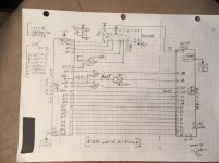
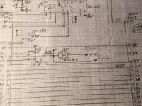
I recently documented the schematic of my 81-212 which was modified to 81-212A.
The way the reset line ended up is J9-45 on the Kaypro connects to 74ls00 input pins 9 and 10 and also is pulled up with a 1K resistor to VCC. The output goes to the WD1002 pin39 (MR*).
To revert the assembly to the 81-212 condition, a 3 pin jumper on the output pin 3 could allow for an either or jumper setup.
For 81-212 a trace from input pins moves parallel to the output pin. The output is cut and 2 pins on either side of the cut allow the input pins to connect directly to the WD1002, pin39.
For the 81-212A, remove the jumper and reinsert to the original connection from pin 3 to pin 39 of the WD1002, pin 39.
A single board easily reconfigured.
If added to the schematic I generated (and will attach here if possible) a board layout can make those adapters easier to obtain.
===================
Single intermediate board K-10 to WD1002
Hey Sharkonwheels,
I recently documented the schematic of my 81-212 which was modified to 81-212A.
The way the reset line ended up is J9-45 on the Kaypro connects to 74ls00 input pins 9 and 10 and also is pulled up with a 1K resistor to VCC. The output goes to the WD1002 pin39 (MR*).
To revert the assembly to the 81-212 condition, a 3 pin jumper on the output pin 3 could allow for an either or jumper setup.
For 81-212 a trace from input pins moves parallel to the output pin. The output is cut and 2 pins on either side of the cut allow the input pins to connect directly to the WD1002, pin39.
For the 81-212A, remove the jumper and reinsert to the original connection from pin 3 to pin 39 of the WD1002, pin 39.
A single board easily reconfigured.
If added to the schematic I generated (and will attach here if possible) a board layout can make those adapters easier to obtain.
===================
Found the explanation of the small circuit board in early and later Kaypros (TurboROM v3.4 Manual, appendix H, page H-4):
H.3. Early Kaypro 10 Upgrade 81-303, Explanation
The two versions of the small circuit board differ primarily in
how they generate the master reset signal for the hard disk
controller board. The early version connected the second floppy
disk drive select signal directly to the hard disk controller
master reset. The later version of the small circuit board uses
the inverted second floppy disk drive select line for connection
to the hard disk controller master reset.
The modification to the early version of the small circuit board
detailed in this appendix inserts an inverter into the master
reset logic for the hard disk controller. The addition of the
inverter makes the early board functionally equivalent to the
later version.
Note: The original Kaypro utilities PUTSYS.COM, PUTOVL.COM
and FMT305.COM, which were provided with the computer
should not be used after these modifications. If you
are inserting the Kaypro 81-302 ROM, replace these system
utilities with versions from a later model Kaypro 10. If
you are inserting the TurboROM, the utilities
TURBOGEN.COM and K10FMT.COM, provided on the TurboROM
Support Software Diskette, should be used.
The actual modification of the early board (TurboROM v3.4 Manual, Appendix H, page H-3):
5. Modify the Small Circuit Board
Make the following changes to the small circuit board.
Keep the wiring short and as neat as possible. The set
of 50 pins will be referred to as J1; the set of 40 pins will
be referred to as J2. On the solder side of the circuit
board, a square solder pad identifies pin 1 of each set of
pins. All pins in the row with pin 1 are the odd numbered
pins, all pins in the other row are even numbered pins. Refer
to Appendix E for basic information concerning the pin
numbering of IC's. Wires should be installed on the solder
side of the circuit board.
1. Cut the trace that runs from J1 pin 45 to J2 pin 39.
2. Cut the trace that runs from U1 pin 7 to U1 pin 2.
3. Add a wire from U1 pin 1 to J1 pin 45.
4. Add a wire from U1 pin 3 to J2 pin 39.
5. Add a wire from U1 pin 2 to U1 pin 14.
Ref: Plu-Perfect Systems Advent TurboROM V3.4 Manual (text version: ftp://ftp.mrynet.com/operatingsystems/Kaypro/Private-Images/TROM-DOC/Turbo_Rom.txt )
From what a few of us here gathered, it looks like the KayPlus is looking for the early mid-board, and not the later one. It never releases the reset on the WD1002.
Also, historically speaking, the way we've adapted the 27(c)64 EPROMs to work in the K10/83 with 24-pin socket, was to tie pins 26,27,28,and 1 together, and then jumper from P2 on the 2764 to p2 on the Z80.
Attachments
jbemond
Member
jbemond
Member
Hi,
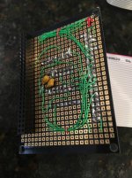
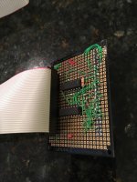
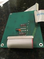
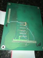
After months of delays, I finally welded and tested the cards needed to run the FreHD on several Kaypro, I test first on a Kaypro 4/84.

Now for two days I try to format three FreHD on a Kaypro 4 (I guess it's a model 4)
View attachment 45348

I tried with both eprom : TROM34.ROM and KPLUS84.ROM
KayPlus not speak with the FreHD...

On the SD card that I formatted in FAT32, I put a disk image "hard4-0" that I had with the CDROM when I bought the PCB.
It is normally 15MB ... but I do not understand how it could be compatible with both the TRS80 and the Kaypro ...
Sometimes I managed to recognize the disk and it is possible to format, even if I have a doubt what it does, the LEDs never flash during formatting.


On the other hand, they flash during the surface test, I filmed if you want images.
but in the end in any case, it does not work
I can not access the disc while exiting the formatting software.
I detail my tests:
With the KayPLUS ROM and the software suite of 1986, I have curiosities ...
If I run HDCNFG.COM no problem, it goes well.
I create a 5MB disk that I name FREHD
to see the photo :
I followed the discussions here, but there are things that escape me ...
<Http://www.vcfed.org/forum/archive/index.php/t-40809.html>
Reading the doc of the FreHD that I had on the CDROM when I bought the PCBs, I saw that it needed disk images?
The problem is that the images provided on the CDROM are for TRS80, in doubt I tried but nothing, it does not work
Also saw that you write about VHDUTL or the kaypro version KHDUTL, is it useful to configure the FreHD on Kaypro? And if there is not someone who already has the .com file, just to avoid having to find a PC, install a cross-assembler just to make an executable version ...
I do not even know if the FreHD works well ... As I understand it, with VHDUTL I could check that the card answers correctly.
At this point, there I start to tell me that I bought three cards and converter cards for nothing and it kills me ...
So I'm asking for help, I think my main problem is that I do not have a good hard disk image, which could have given me one or more specific because I have 4 FreHD I would like to install in the following Kaypro: Kaypro II, Kaypro 2X, Kaypro 4/84, Kaypro 10
Thanks for your help,
JB
For me it's really not easy I have trouble with English, so write a message or I have to explain in detail what I do and what works or not it's hell
After months of delays, I finally welded and tested the cards needed to run the FreHD on several Kaypro, I test first on a Kaypro 4/84.
Now for two days I try to format three FreHD on a Kaypro 4 (I guess it's a model 4)
View attachment 45348
I tried with both eprom : TROM34.ROM and KPLUS84.ROM
KayPlus not speak with the FreHD...
On the SD card that I formatted in FAT32, I put a disk image "hard4-0" that I had with the CDROM when I bought the PCB.
It is normally 15MB ... but I do not understand how it could be compatible with both the TRS80 and the Kaypro ...
Sometimes I managed to recognize the disk and it is possible to format, even if I have a doubt what it does, the LEDs never flash during formatting.
On the other hand, they flash during the surface test, I filmed if you want images.
but in the end in any case, it does not work
I can not access the disc while exiting the formatting software.
I detail my tests:
With the KayPLUS ROM and the software suite of 1986, I have curiosities ...
If I run HDCNFG.COM no problem, it goes well.
I create a 5MB disk that I name FREHD
to see the photo :
I followed the discussions here, but there are things that escape me ...
<Http://www.vcfed.org/forum/archive/index.php/t-40809.html>
Reading the doc of the FreHD that I had on the CDROM when I bought the PCBs, I saw that it needed disk images?
The problem is that the images provided on the CDROM are for TRS80, in doubt I tried but nothing, it does not work
Also saw that you write about VHDUTL or the kaypro version KHDUTL, is it useful to configure the FreHD on Kaypro? And if there is not someone who already has the .com file, just to avoid having to find a PC, install a cross-assembler just to make an executable version ...
I do not even know if the FreHD works well ... As I understand it, with VHDUTL I could check that the card answers correctly.
At this point, there I start to tell me that I bought three cards and converter cards for nothing and it kills me ...
So I'm asking for help, I think my main problem is that I do not have a good hard disk image, which could have given me one or more specific because I have 4 FreHD I would like to install in the following Kaypro: Kaypro II, Kaypro 2X, Kaypro 4/84, Kaypro 10
Thanks for your help,
JB
For me it's really not easy I have trouble with English, so write a message or I have to explain in detail what I do and what works or not it's hell