• Please review our updated Terms and Rules here

KIM-1 repair

@daver2 - I did read about the 1.0A to 1.2A requirement, but that seems excessive to me. Does anyone know what the actual current requirement is while up and running?

@Dwight Elvey - Yes, I do know quite a bit about the various interface adapter ICs and their pinouts. The XIA currently has support for:

6520 PIA
6521 PIA
6522 VIA
6523 TPI
6525 TPI
6526 CIA
6530 MIOT/RRIOT
6531 RRIOC (Vcc on pin 21 instead of 20)
6532 RIOT
6821 PIA
8520 CIA
8521 CIA

This is a project that I started before the pandemic, became a victim of the parts shortage, and then lost interest really. Now I am back on this project. For the 6530, I have a slew of masked ROMs that people have sent me, along with schematics to determine the state machine requirements.

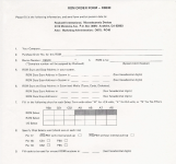
Which pinball machine do you have? Allied used 6530-06 through 6530-11 for their pinball machines. There were also a couple Gottieb sound boards that used the 6530. I have the ROMs and state machine info for these. I can't provide ROM code (copyright reasons), so I have made the XIA so that you can upload the ROM to it and then select the state machine functionality. This is the same method used originally when ordering a new part from MOS, Rockwell, or Synertek (see attached example for the Rockwell order form).

RE: the KIM-1, I am going to have to change the sockets because there are literally some pins that are not soldered (move freely).
 

Attachments

  • Clipboard01.png
    Clipboard01.png
    1.4 MB · Views: 8
I can't help you with the actual current draw as I don't have a real KIM-1.

There are a couple of capacitors and a zener diode directly across the +5V and 0V power rails, so it would be worth checking these first.

Dave
 
Interesting project @JimDrew , I hope you succeed.
My KIM-1's current draw was about 500-700 mA with all the ICs in. The large ICs U1-U3 and the display do consume a bit of power
 
Thanks for confirming your current consumption. I don't have a choice about changing the sockets, so I will do that and then try with 1A of current output and see what happens. :)
 
I have been sorta sucked down the rabbit hole repairing this KIM-1, so I ended up fully recreating the keypad (exactly like the original). I am having some samples made (hires SLA) and I might end up having these injection molded. I know there is probably not a huge demand, but this will also work with a different PCB I designed (no membrane overlay) for the replica KIM-1 boards out there as well.
 

Attachments

  • Clipboard_09-13-2024_01.jpg
    Clipboard_09-13-2024_01.jpg
    306.6 KB · Views: 15
  • Clipboard_09-13-2024_02.jpg
    Clipboard_09-13-2024_02.jpg
    288.7 KB · Views: 15
  • Clipboard_09-13-2024_03.jpg
    Clipboard_09-13-2024_03.jpg
    227.7 KB · Views: 15
Nice job !

Sucked down the Rabbit hole eh ? Welcome to vintage computing, I'm sucked down the Rabbit hole too on a vintage computer repair and I think I'm about to become the Mad Hatter.
 
Thanks! I am not exactly new to vintage computing.... this is just a new rabbit hole. :)
 
Thanks for confirming your current consumption. I don't have a choice about changing the sockets, so I will do that and then try with 1A of current output and see what happens. :)
Jim, did you make any progress on the 6530 replacements? As predicted by Dave, it's hard finding one
 
Yes and no. Yes, the design is great but there is a race condition in the hardware emulation (for most chips that the XIA emulates) that I am working through... it's been an interesting dilemma because I need a logic analyzer with at least 38 channels. So, I got a HP/Agilent 16702A and a slew of cards for it. I have friends who also got the same setups. All of our setups are bad because the cards are all bad. The 3M adhesive that is used to hold plexiglass runners on the cards (to prevent them from scraping into the motherboard) has eaten through the soldermask and copper traces! These are nearly impossible to fix. After searching for something affordable (and giving up) I found out about the Pico based analzyer and I am getting ready to build and test the latest version that can be daisy-chained together to give you up to 120 channels, supporting 200MHz on each channel which is way more than I need for this. So, the project is in limbo until I can look at the line states with a LA. I should have the design files literally any day for the new Pico analyzer, and I will rush to get boards made.
 
Last edited:
That sounds great, and sorry to hear about your logic analyzers... It seems like those Picos are a real saviour in the vintage computing world
 
Back again trying to fix this ill-fated machine. First of all it ate up another 6502 or it died of old age, I'm left with a 65c02.

I borrowed reDIP riot chips, untested of course.

In any case it passes the RAM tests and shows this mess on the displays:


Any ideas what it could be?

It also behaves erratically but I don't know why, sometimes it runs sometimes it crashes or flickers or resets. Maybe if I sort the displays I can circle in on the other problem(s).
 
I helped fix a KIM-1 with display issues via Direct Messages.

I will post how we did it tomorrow.

How many of your devices are in IC sockets?

The 'weird' non-hex characters look like ROM problems.

Dave
 
Thanks for additional information, I think something is wrong with the display driving logic (as every other 7 segment display doesn't show anything), but at the moment I don't know enough... especially if the FPGA RRIOTs are working correctly.

The 40pin DIPs, U4 and half the RAM ICs are in sockets. If you have something in mind to test I can also desolder it.
 
If U2 is in an IC socket, remove it please.

None of the segments on any of the displays should illuminate.

PB1-PB4 of U2 will be floating. These signals go to the DCBA inputs of U24 (74145). An unconnected TTL input generally floats high. The DCBA inputs to U24 are all (therefore) high. This presents an illegal decimal code to U24. As a result, all of the U24 outputs should be high (well, more correctly, open circuit).

All of the transistors driving each digit should be fully switched OFF (due to the base resistors R18... pulling the base of the PNP transistor to +5V - the same potential as the emitter). As a result, there should be no supply to the common anodes of the 7-segment displays, and nothing can illuminate.

With U2 being removed, PA0-PA6 will also be floating. The inputs to the inverter gate U17 will also be floating, so should float high. This will cause the outputs from the inverters to be pulled low. This should be pulling the cathodes of each of the segments low.

However, nothing should still illuminate because the anode transistors are switched OFF, so no current can flow in the display LEDs.

If you have a logic probe, check that all of the outputs from U17 are LOW.

If not, connect a multimeter (set to read Volts) with the positive probe connected to +5V and use the negative probe on each output of U17.

The multimeter should read +5V when the negative probe is connected to each output of U17.

Next, we will try and turn a digit on...

Dave
 
I spent a bit of time looking at your video. I suspect you have two (2) faults with your display - one fault driving the digits and another fault driving a segment.

I suspect the 'digit' fault is U24 pin 15 stuck HIGH. This is PB1 from U2. Check that U2 pin 24 is making good contact, and that there is conduction from U2/24 to U24/15. If this is OK, check to see if U24 pin 5 is actually changing state or just stuck.

The occasional funny hex character display is related to segment 'b' being stuck ON.

This could be U2/40 (PA1) to U17/13 stuck HIGH, or U17/12 stuck LOW.

I also forgot that U17 drives 6 of the 7 display segments. U26 pin 3 drives segment 'd'.

Dave
 
Last edited:
Thanks for the pointers Dave!

I fixed the erratic and random behaviour, it turned out to be bad power supply cabling. But still some work to do.

U24 pin 5 doesn't change state and PA1 neither, with the reDIP chip in it.

With the original 6530-002, the number counting works without problems (and U24 pin 5 does change state) , but the next test doesn't show the checksum. This confirms at least the transistors and parts of the logic driving the LEDs working.

With the replacement chip in it, I can see the ROM checksum test flicker the correct checksum, but also very randomly and sometimes with digits or segments missing.

Some signals (A4, D0, D1) look like they have a conflict or aren't otherwise driven correctly, they are near TTL nirvana (~2 V)

U24 1-4 look strange too (RW 0-3?)

The keyboard test shows gibberish with both chips
 
Sorry,

U24 pin 5 should be U24 pin 15...

U24 pins 1 to 4 are probably a red herring. U24 is an open collector output. With no keypad buttons pressed, U24 1-4 are either tristate or 0V. There is no pullup resistor, so there should be no logic HIGH anywhere, other than stray resistance/capacitance.

Dave
 
Last edited:
You need a good power supply as the first thing (as you have just found out).

Next, you need a reliable clock. Check U16 pin 10 for this. The crystal oscillator should be nice and constant.

Next, it would be useful to see another video of what is occurring on the displays with various of Dwight's tests running.

We can take it from there.

Dave
 
Hi Dave

I checked the clock and reset right after the voltages!

After chasing a lot of ghosts (it included unnecessarily changing the CPU socket and U14), I found out that the problem is somewhere on the debug board, which was pulling the aforementioned signals low.

I burned a new EPROM but now my debug board doesn't run at all (even though both EPROMs verify correctly)

On the positive side, with the board turned off it appears that I have a working KIM-1:

20260107_162418.jpg

It also seems that the CPU wasn't broken after all, just that the 65c02 was more tolerant of the errorenous signals.

The 6530-002 is definitely broken, I don't get digits with it inserted.

Still, something else could be wrong but progress at least...
 
Back
Top