• Please review our updated Terms and Rules here

KIM-1 repair

Keyboard = Keypad.
Video display = 7-segment LEDs.

What Dwight is saying is that his test EPROM is mapped into the KIM-1 memory map even when you are running the 'standard' KIM-1 monitor code.

You can, therefore, execute the test code (depending upon the switch settings) from the KIM-1 monitor.

You can connect a 20mA current loop terminal to the KIM-1. Follow the instructions in https://web.archive.org/web/20141129191838if_/http://archive.6502.org/books/kim1_user_manual.pdf. See figure 2.4.

If you are unaware of how to use the KIM-1 monitor, I would advise that you do a bit of reading. It may be working correctly, but you do not know it yet!

Dave
 
>>> In this case it's not necessary, because I managed to punch in the example code from the manual and run it (I think.. still not too sure.. got 05 and FE from page 12). The keyboard and display look ok to me.

05 and FE are the correct answers.

That does (sort of) indicate that the KIM-1 debug monitor, keypad and 7-segment displays are working.

So, the reason for the diagnostic tests not working must be "user trouble".

As Dwight says, there is an Asteroids game built into the diagnostic EPROM.

I use the March-C tests in my PETTESTER - the source code is available for people to re-use the algorithm.

Dave
 
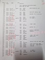
If you can enter and run a program, you should be able to use the KIM-1 keypad and display to examine the 6530 ROM and compare the results you obtain with the listings in the KIM-1 manual...

Press the [RS] (Reset) key.

Press the [AD] (Address mode) key.

Enter the address 1800 using the hexadecimal keys.

Press the [DA] (Data mode) key.

The debug monitor should display the byte stored in the 6530-003 ROM at address 1800.

According to the manual (https://forum.vcfed.org/index.php?threads/kim-1-repair.1248642/page-4 PDF page 117 of 138) the displayed value should be A9 at this address.

Press the [+] key to move on to address 1801. The displayed value should be AD. Keep pressing the [+] key to advance through the 6530 ROM memory.

This is a little bit of a "ball ache" - so I would suggest printing out the relevant pages from the KIM-1 manual and crossing each byte value off as you go. Do the data bytes in sections, and you will get through it in a pretty short period of time...

The 6530-003 ROM occupies addresses from 1800 to 1BFF.
The 6530-002 ROM occupies addresses from 1C00 to 1FFF.

Any discrepancies, please report the address, what the byte should have been, and what you observed.

If the 6530 ROM checks out OK, the next check would be the 6530 internal RAM.

Dave
 
Unfortunately I don't have any devices with a 20mA current loop terminal interface...

It's getting worse again.

I checked the first page of each listing, where the addresses from U3 are as attached and U2 was completely fine.

I then moved on to the EPROM location 0C00 and 0E00. Apart from the odd mistake here and there (with U2 in, the first wrong byte being at 0E16) the data display at 0E50 started glimmering with random values. It was getting worse or better while flexing the board and now I lost the monitor again. It completely ignores the DB setting and immediately executes the code in the EPROM (with test 0 being the only one correctly executing while U2 is in).
 

Attachments

  • kim-1-6.jpg
    kim-1-6.jpg
    1.2 MB · Views: 4
So, you either have some faulty IC sockets or some of the PCB tracks are intermittently becoming faulty. If the PCB is two layer (which it will be) then there will be vias from one side of the PCB to the other. Sometimes these become intermittently faulty.

You just have to work through the problem.

I would use a multimeter (power off and set to Ohms) to ensure conductivity from each pin of every component to all other pins on the same PCB track whilst flexing the PCB.

Sorry, no magic bullet for these types of problems apart from hard slog and a slice of luck...

Dave
Very good thoughts.

Vias can split with a 360 degree ring crack just after the copper dives into the hole. In cmos circuits at least, this can produce what appears to be intermittent behavior for a couple of reasons. One is that it can leave the gate of a chip with an open input, and functions can come and go depending on its electrostatic charge and therefore gate voltage. The other is, it picks up interference dynamically and changes the logic output. The flickering display could be an indicator of such a problem.

Vias can fail for other reasons such as previously leaked electrolyte on the pcb, though I'm not sure if the KIM-1 has any likely to do it.
 
If you recall I mentioned that the board had sockets. I just don't recall any original KIM-1 with sockets. These boards were really cheap. I consider myself as better than most all at removing components from PC boards without issues of breaking traces. Still, I broke one via when I socketed my board. It sounds like the board you have has good looking solder joints but that has nothing to do with if the vias are good.
If you have a bad via, I often take a small piece of wire wrap wire and stick it into the off ending hole while the solder is melted. Usually there is enough room in a IC or socket hole to add the wire.
If you have an intermittent via, you can try using a probe made with a D sized battery cell and a meter. Driving a current through a weak via will often make it fail.
You put the meter in parallel with the battery so it measures the voltage. When measuring from top to bottom of the board, a good trace will measure close to 0V. A completely open will measure the battery voltage.
The other thing is that it may be a failing part. You might look with your thermal imaging again.
Something, too hot or too cold could indicate a bad part.
Dwight
Excuse, but how to attach a video output to the KIM-1? Is this a serial terminal type application or analog video? I've never used a KIM-1 before this thread...


If possible, you could give some pointers I could try to figure out how to adapt the code?


I saw that there is a white ceramic variant of the KR565RU2, but of course it's more expensive and also harder to get. It's used in some eastern block mainframe memory boards, but removing them from such a board would present a similar dilemma as in your previous post
I don't recall if one can do block letters with a KIM-1 to a video but it seems like I recall seeing it done.
As for 20 ma serial, it is not real hard to make a converter using a couple optical isolators and one of the Maxim chips with built in capacitor for charge pump, to get to RS232 levels. Many optical isolators won't run at 9600 baud but 1200 is quite commonly done.
 
Here is an example:
The problem with your board could be the sockets. See if you can find a can of NoOx ( sp?) that you can spray on the sockets.
Flexing the board is a good indicator of poor contact someplace.
Dwight
 
If you recall I mentioned that the board had sockets. I just don't recall any original KIM-1 with sockets. These boards were really cheap. I consider myself as better than most all at removing components from PC boards without issues of breaking traces. Still, I broke one via when I socketed my board. It sounds like the board you have has good looking solder joints but that has nothing to do with if the vias are good.

U1-U3 were socketed from factory on my board. I haven't found the issue yet.

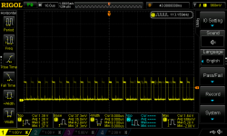
I don't understand it, with U2 inserted there is AB4, pin 8 of 6502 with too low signal levels. If it has a signal resembling data or not is random on each RS press (sometimes it's just a flat line at 1.5-ish Volts).
DS1Z_QuickPrint29.png
Without U2 I don't have this. Is a problem with U2 exclusively? Can I safely insert the U3 6530 and vice versa in U2 to see if it follows the position in the board or the IC itself?

If those single wipe sockets can be an issue I'll try to replace them (all the inserting and removing sure didn't do them any good). For now I'm still not sure what it is. I did spray contact lubricant in them otherwise they wouldn't survive for long.
 
U1-U3 were socketed from factory on my board. I haven't found the issue yet.

I don't understand it, with U2 inserted there is AB4, pin 8 of 6502 with too low signal levels. If it has a signal resembling data or not is random on each RS press (sometimes it's just a flat line at 1.5-ish Volts).
View attachment 1283503
Without U2 I don't have this. Is a problem with U2 exclusively? Can I safely insert the U3 6530 and vice versa in U2 to see if it follows the position in the board or the IC itself?

If those single wipe sockets can be an issue I'll try to replace them (all the inserting and removing sure didn't do them any good). For now I'm still not sure what it is. I did spray contact lubricant in them otherwise they wouldn't survive for long.
I don't think that is pin 8. Pin 8 is VCC?
I don't think it will do any damage to put U3 IC in socket U2. I don't think it will work the keyboard or display, though.
RS0, pin 4, is for the ROM only.
CS1, is for the I/O but is decodes the address lines differently, for -002 and -003. The select pins are mask programmed.
Since both chips uses the same K5, to their CS1, they'd have different address decoding inside for their I/O.
I should ask, does the RAM test run without U2 or U3. If not they are not likely the problem.
Dwight
 
Can you just post a photograph of your Kim-1, especially the arrangement (orientation) of the three 40-pin chips in relation with the others.

Dave
 
I don't think that is pin 8. Pin 8 is VCC?
Sorry, pin 13 of the CPU (AB4)
I don't think it will do any damage to put U3 IC in socket U2. I don't think it will work the keyboard or display, though.
RS0, pin 4, is for the ROM only.
CS1, is for the I/O but is decodes the address lines differently, for -002 and -003. The select pins are mask programmed.
Since both chips uses the same K5, to their CS1, they'd have different address decoding inside for their I/O.
I should ask, does the RAM test run without U2 or U3. If not they are not likely the problem.
Dwight
Tests 0, 1, 2 (2 only showing the blinking LED of course) run fine without the -002 chip, they run also run fine with the -003 inserted in any position and they don't run anymore with the -002 in any position U2 or U3
I think it has had its last hurrah in the posts before and has now failed completely with by pulling the AB4 line too low
Can you just post a photograph of your Kim-1, especially the arrangement (orientation) of the three 40-pin chips in relation with the others.

Dave
I can in the evening if you really want to, but I always took care to place them correctly. The sockets have notches too so it's not too hard to mix it up.
The CPU is upside down and that might have been why the original CPU failed.... all the electrons have fallen out by now!
 
Not necessary then.

It was just the orientation of the ICs I was interested in, and you appear to have that covered...

So AB4 is an address line input to the 6530, so (if the 6530 is pulling the line low) it must be a faulty input protection diode - or something fairly close to the IC pin internally.

Not sure what bearing this has on the 'pressure sensitivity' of the board though. Or perhaps this is an unrelated issue?

6530 adapter board next? Or do you have a spare 6530-002 available?

Dave
 
Not sure what bearing this has on the 'pressure sensitivity' of the board though. Or perhaps this is an unrelated issue?
This was (or is) an additional issue. The problem I described where it would execute the debug board code even though DB was off, eventually went away while handling and flexing the board, or taking an IC in and out of its socket, not sure what did it in the end. I made a mental note about it.

6530 adapter board next? Or do you have a spare 6530-002 available?
I don't have either of these and will come back to this thread when I do...
 
I see Dave replied about the AB4 line.
I was thinking about the adapter. A fellow in Canada has created a schematic of my 6532 to 6530 adapter ( stuff I lost being clumsy ). Some one might use it for their own PC board.
He created the PAL code so one could use what ever they liked. I hand made the original data file for the PAL without using PALASM or similar tool. My original rats nest test adapter was done using small surface mount TTL's.
I wanted to have every thing to fit under the IC socket but it would be more practical to stretch a single board out the top end. I'd have stayed with the surface mount TTL but it just wouldn't all fit under the 40 pin socket. With the PAL, I could choose best location for inputs and outputs for easiest routing.
Doing the pin scramble of the 6530 to 6532 pins is a pain. If I was doing it with a full sized EEPROM ( 28 pin package ) I'd deal with less PC board for traces de-scrambling and use some point to point wires to un-scramble many of the pins. That would leave more room to run traces out to the PAL or GAL logic and EERPOM. Some times it doesn't make sense to put everything as traces on the PC board.
Because of the tightness of squeezing everything under the 40 pin socket, I did two levels of board ( 4 layers ) but it could be a single double sided board, if one wasn't restricted to such tight spaces.
When looking at the schematic, one might say some of the wiring, especially to the EEPROM, looks mixed up. This was done this way for 2 reasons. One was routing and the other was making the right signals on the EEPROM to be able to use the KIM and debug board to do the programming of the EEPROM. There was nothing sacred about A0 address going to A0 of the EEPROM and such. It just needed 1K of address decode. The same rule applies to data lines. It was much easier to modify the program to make it practical to program the EEPROM on the KIM than to worry about correctness of pin labels.
Anyway, if you are interested in doing your own board, I can send the schematic to you. RUUD also has a schematic that would work well for -002. It does have some flaws for -003 in interrupt controls. His routing for the EEPROM would require external programming or use a regular EPROM and programmer.
Dwight
 
Hi gang... new KIM-1 owner here. Can someone tell me how much current this thing really needs to power up? I have it connected to a lab power supply and I set it at 5V@200mA and it pulls the voltage slowly down to about 2.25V.. so something is pulling a bunch of current and I am not sure if it is "normal". This is with all of the ICs in place. I don't get any display activity and I did not push my luck leaving it on for more than a few seconds.

This KIM-1 is a bit of a disaster. It's a Rev G with factory white sockets for the 40 pin DIPS, and some (not so talented with a soldering) person tried to put their own 14 & 16 pin sockets in, and so there are super questionable connections at the sockets. I am going to remove all 17 sockets and replace them, first testing the top/bottom continuity to make sure the through hole is still good (I am assuming there are plated through holes - I didn't check).

I made a few of the KIM-1 replica boards (from the scan that Chuck made), and I have the parts for them but I found this real one for about 1/2 of the going rate and since I need to have one (working) to test the XIA that I am making, I figured why not. The XIA is a programmable replacement "chip" (40 pin DIP package) that can emulate virtually any type of CIA/VIA/PIA/RIOT/RRIOT/etc. including all 47 known versions of the 6530. I have quite a few things that use the 6530 and some friends with some of the oddball stuff (like gambling machines). You can upload a ROM mask and set the state machine configuration, much like you could order the 6530 originally.

I ordered the debug board PCBs. Those will be here in a week or so. I will build one of those for testing, but right now I would really like to know what the normal operating current is for this thing. Thanks!
 
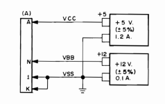
If you look in the user manual you should see we are talking about +5V at 1.0A to 1.2A.

1725103789290.png

200 mA is way too low and will just cause the power supply to current limit (as it has done).

Dave
 
Hi gang... new KIM-1 owner here. Can someone tell me how much current this thing really needs to power up? I have it connected to a lab power supply and I set it at 5V@200mA and it pulls the voltage slowly down to about 2.25V.. so something is pulling a bunch of current and I am not sure if it is "normal". This is with all of the ICs in place. I don't get any display activity and I did not push my luck leaving it on for more than a few seconds.

This KIM-1 is a bit of a disaster. It's a Rev G with factory white sockets for the 40 pin DIPS, and some (not so talented with a soldering) person tried to put their own 14 & 16 pin sockets in, and so there are super questionable connections at the sockets. I am going to remove all 17 sockets and replace them, first testing the top/bottom continuity to make sure the through hole is still good (I am assuming there are plated through holes - I didn't check).

I made a few of the KIM-1 replica boards (from the scan that Chuck made), and I have the parts for them but I found this real one for about 1/2 of the going rate and since I need to have one (working) to test the XIA that I am making, I figured why not. The XIA is a programmable replacement "chip" (40 pin DIP package) that can emulate virtually any type of CIA/VIA/PIA/RIOT/RRIOT/etc. including all 47 known versions of the 6530. I have quite a few things that use the 6530 and some friends with some of the oddball stuff (like gambling machines). You can upload a ROM mask and set the state machine configuration, much like you could order the 6530 originally.

I ordered the debug board PCBs. Those will be here in a week or so. I will build one of those for testing, but right now I would really like to know what the normal operating current is for this thing. Thanks!
I'm sure you know that the 6530 parts to not have typical power supply pins.
When I did my replacement part, I had to figure how the select pins were configured. The ROM is mapped differently than the RAM and I/O.

Do you have a list of the configurations for the various 6530s? I have a pinball machine that the sound chip is blown up. It was my fault, when I got a used replacement board, I didn't check the connections of the 5V regulator screws. Without the ground connect the voltage goes to 12V and poof, the magic smoke was gone :(

As for the feed thru holes, They are plated but easily damaged.
I usually put a piece of 30 ga wire through the hole and tack it to top if I question the connection. Keep us informed on your project progress.
I should note that Ruud's schematic is not fully compatible because of the Interrupts. Not many people use interrupts on there KIMs. I believe mine should be but it has not been tested.
Dwight
 
Last edited:
Back
Top