• Please review our updated Terms and Rules here

M24SP DB25 to DB9 adapter

The pinout you posted, is that an official Olivetti document? It looks li,e something fanboyish, not degrading the producer, just that if it's not an official Olivetti document, it's not official.

I would not expect a cga compatible monitor to work. Chances are you won't damage it by simply testing. But perhaps best to exercise caution.

Assuming through outputs are r,g,b,i, you would need some probably simple circuitry to "add" intensity to the other 3 when appropriate. I could probably come up with something in a couple hours, assuming I had the time and inclination, and I'm no whiz. Ask around on electronic forums, or look at circuit examples in books.
 
The document is fanboyish, that's why I didn't trust it, but I was not able to find an official document with the pinout.
However, the initial question has been answered,
- PIN7 has INTENSITY and
- we have a digital TTL output, not analoge.
- The VGA adapter allows only 8 colors and not 16.
- It is not possible to connect my RGB monitor since it doesn't support the proprietary 25khz signal from the M24(SP).
 
The official document was provided. You're likely correct, but there may be more to the story. That document also shows ID and mode pins. So who knows...
 
You have interference all over that first screen, not just in the blue. If you look on the screens where our have solid colors, you have solid colors. If i understand you. As the the reason I can't say.
 
i later read somewhere that the m24 always uses the 640x400 mode, even in text mode, hence it has a 8x16 text mode font instead of 8x8.

how ever - i built an adapter today and imagine what... i see correct colors and... a picture!

M24 proprietary DB25 <-> DB9 standard RGB
PIN# - PIN#
1 - 8
3 - 9
4 - 3
5 - 4
6 - 5
7 - 6
14 - 1
15 - 2

proof that we have TTL and that it is possible to connect the olivetti m24 to any 3rd party RGB-I screen that can handle a line frequency of 25khz and that its worth trying it.

sadly my cm8833-II can't correctly display the 640x400 mode that the olivetti outputs and it generates a high-pitched tone and the picture is compressed to the half height. i turned it off after 1 minute for safety reasons and will not try it again.
 
I wonder, above you wrote, that the M24 always fires out 640x400, even in text mode, but then when it switches to real 640x400 mode, then your monitor can't display correct? Otgerwise, are you sure that your Philips is in TTL mode? I think I have the same monitor, and it's switchable between TTL and analogue.
 
OK guys, here is my last update to this.

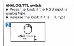
Knob explanation:
Unbenannt.JPG

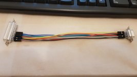
The adapter in use:
20180824_220257.jpg

Pinout as mentioned:
M24 proprietary DB25 <-> DB9 standard RGB
PIN# - PIN#
1 - 8
3 - 9
4 - 3
5 - 4
6 - 5
7 - 6
14 - 1
15 - 2

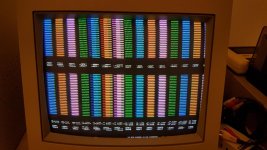
The knob on my screen released - TTL mode:
20180824_215511.jpg

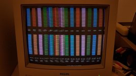
The knob on my screen pressed - Analog mode:
20180824_215655.jpg

As you can see I have correct colors in TTL mode (upper line is dark, lower line has intensity/high bit set and is brighter) and in analog mode, similar to a standard RGB device I have (Bondwell B200), not.
The M24 definitely has a TTL output but 25khz thus my CRT cant handle it correctly and displays the above garbage.

Also the blue line mystery is solved, it's mentioned in the MS-DOS User Guide on page B-5 that you have underline instead of blue foreground color on monochrome monitors.
20180824_221140.jpg

The original Olivetti monochrome monitor uses a complete different PINout than my color monitor adapter.
20180824_221450.jpg
 
Last edited:
Back-of-the-envelope time here. IIRC, the "white" level for VGA is 0.7V. The output of the 6300 display controller is probably within the range of 0.3 to 4.8V (driven by an 74LS244). So, to get 16 colors, you'd need to use the highlight signal to clamp the levels down to about 2.5V or less to get visible differences. You could also include "brown" correction for the "dim yellow" like the IBM CGA monitor does.

I finally got my hands on a VGA monitor that is compatible with the 6300 and I'd like to have a go at this - any pointers on how one would approach this? The output stage of the 6300 display controller is indeed TTL - a 74S374 latch. For the sake of simplicity let's assume we have access to a 5vdc rail (possibly regulated down from the +15vdc on the video connector).

Thanks!
 
A VGA monitor can't be compatible with the M24/6300. Please forget about the idea from ChuckG and disable the internal graphics card and use a 8bit VGA card instead.
 
A VGA monitor can't be compatible with the M24/6300. Please forget about the idea from ChuckG and disable the internal graphics card and use a 8bit VGA card instead.

Uhm... I'm actually using one right now, and quite a few people have done so in the past as well :)

The well-known adapter works well but it can only display 8 (2^3) colours. It would be nice to try and design an adapter that makes use of the Intensity pin and displays the full 16 color range.
 
Since I no longer own a 6300 to try this out on, it seems to me that a simple resistive divider with a tap driven by 3 CMOS gates connected to the intensity line should do the trick.
 
The well-known adapter works well but it can only display 8 (2^3) colours. It would be nice to try and design an adapter that makes use of the Intensity pin and displays the full 16 color range.
Such adapters exist and there is no need to build something. They are called "RGB to VGA converter".
 
Now, freakedenough may have a point regarding usability. But whatthehell, why not just scrap the innards and install an RPi with HDMI interface? Less power, more speed and higher resolution and wider palette.

But if you want to run some M24/6300-specific application that uses the 16-color capability and resolution natively, a VGA card won't help you. You'll note that early on, I did suggest disabling the internal video and using a VGA card. But the OP is clearly after the original experience, which is why he doesn't use an RPi as an emulator.

Why do folks use a CGA with their 5150 or 5160? A VGA card would be far more flexible... An i7 motherboard would be much faster...
 
Since I no longer own a 6300 to try this out on, it seems to me that a simple resistive divider with a tap driven by 3 CMOS gates connected to the intensity line should do the trick.

I was thinking along those lines as well - essentially some variation of a 2-bit R-2R DAC driven by logic gates with the MSB equal to (Colour AND Intensity) and the LSB is just the Colour (R, G, or B). I was a bit concerned about speed - the propagation delay on, say, a 74HCT08 is stated as 15ns, which is a significant proportion of the pixel "time" (1/pixel clock = 40ns @ 24MHz). I guess the MSB and LSB can be kept in sync by having the LSB go through the same gate as well (unchanged, i.e. connecting Colour to both inputs of the AND gate). This may work?
 
I don't work well with verbal descriptions--how about a schematic? You might also look to see what the IBM 5153 CGA monitor does, since it has to deal with the same issue.
 
Back
Top