• Please review our updated Terms and Rules here

Neglected PET needing some love

Although the T48 does look interesting and does allegedly support the 2716, I can't see any mention of the Hitachi or Texas 2532 EPROMs in its device support list - these are the ones which are most useful for replacing failed PROMs in PETs, so it is a great pity the T48 does not support them.
And there are two sorts of 2532's as well to consider.

Also the GQ-4x supports the common 2732A and 2732 in both variants, the 21V or the 25 V programming voltage.

And though the GQ-4x does support the TMS2352JL, it doesn't officially support the TMS2532A for writing to it with the lower programming voltage. However the TMS2352A can still be programmed by it, by using an adapter and setting the GQ-4x for the 2732A variant, so that the correct programming voltage is applied to the TMS2532A.

Because of this though, I have never bothered with the TMS2532A ROMs , I kept away from them and always made sure to buy the TMS2532JL's for my PET, which are just plug & play so to speak, in the GQ-4x. I have had no trouble this way.
 
Last edited:
Wow, you are right. 2816's are getting hard to find. If you have trouble programming the ebay parts, I will send you a programmed part. It is important that you test with daver's PETTESTE2KV04 program as it will help fix the PET.
-dave_m
Thanks that's a very kind offer, hopefully though I should be set with these 2816's.

All this talk about programmers has me looking at different ones. The XGecu T56, which was mentioned, I noticed is around $60 from Ali Express? that seems too low considering the prices from other outlets. Granted I'd have a wait as it gets shipped from China but still...
 
All this talk about programmers has me looking at different ones. The XGecu T56, which was mentioned, I noticed is around $60 from Ali Express? that seems too low considering the prices from other outlets. Granted I'd have a wait as it gets shipped from China but still...
At one time there was a lot of * Fakes * going around, GQ-4x and the Xgecu's, And Probably still are.
 
At one time there was a lot of * Fakes * going around, GQ-4x and the Xgecu's, And Probably still are.
That is funny, a fake modern device like a GQ-4x, probably all are assembled from the same components, from the same sources these days. It might be impossible to tell a fake one from a real one.

With a vintage parts or apparatus, there are many clues & ways to determine if it is an original item, or not. A brand new item however, that is more difficult.

One way to avoid a fake or clone of the GQ-4x could be to contact MCUmall Electronics and ask where their nearest authorized distributor is to your location.
 
That is funny, a fake modern device like a GQ-4x, probably all are assembled from the same components, from the same sources these days. It might be impossible to tell a fake one from a real one.
It's not impossible, Back in the day i'm pretty sure it was MCUmall that reported on the differences to look out for, As Xgecu have done in the past, There were differences in the case, PCB and substandard components were used, Understandably MCUmall would not accept any that were sent in for repair.

One way to avoid a fake or clone of the GQ-4x could be to contact MCUmall Electronics and ask where their nearest authorized distributor is to your location.
Indeed, I bought mine direct from MCUmall, I think i had it within a week of ordering.
 
Alright the 2816's came in today, had no problems writing to it. The pettester is running now. So far other than the glitchy characters until it warms up all seems okay. the rom checksums check out.

The keyboard test is failing (all just stay at 0 no matter what key I press)

When it got to the ram test it said "16k dram memory test"
 
Let the memory test run for a good 10 or 20 passes. This tells us the low bank of 16K is definitely good.

Double check that the ROM checksums are stable and don't change during the countdown.

I will post how to test the keyboard logic out and how to find out problems with the upper 16K bank tomorrow morning if that is OK.

Dave

Okay I had shut it off so I restarted it. The rom checksums didn't change during the countdown. I'll let the ram test run.

Thanks for helping out, I"m in no hurry I knew this would be a long project, haven't even got to what I thought would be the hard part yet (the monitor swap).
 
Some signals to be getting on with...

Check UB12 (6520) pin 18 for pulses (VDRIVE).

Check UB12 pin 37 for similar pulses.

Check UB12 pins 10 through 17 for HIGH.

Check UC11 (74LS145) pins 12 through 15 for pulses.

Dave
 
Some signals to be getting on with...

Check UB12 (6520) pin 18 for pulses (VDRIVE).

Check UB12 pin 37 for similar pulses.

Check UB12 pins 10 through 17 for HIGH.

Check UC11 (74LS145) pins 12 through 15 for pulses.

Dave

UB12:
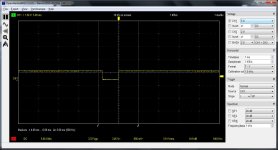
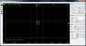
Pin 18: ub12-pin18.jpg

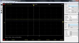
pin 37 is high:
ub12-pin37.jpg

Pins 10-17 are high

UC11 (had to zoom out the timebase for this to 50ms)
Pin 12:
uc11-pin12.jpg

Pin 13 looked pretty much the same as 12.

Pin 14:
uc11-pin14.jpg


And pin 15:
uc11-pin15.jpg


So I'm assuming pin 37 on UB12 being high is not correct.

BTW I did this scoping with the pettester rom in. let me know if I should have put back the edit rom instead.
 
Please continue to use the PETTESTER ROM...

You need to adjust your Y Volts/div to get a reasonably sized signal displayed.

You also need to adjust your timebase to get a couple of cycles of the waveform in view (or a couple of complete cycles on the screen).

There is something not quite right about the input signals on UC11. However, if there are some signals on UC11 you must also have a signal on UB12 pin 37!

I suspect you can't see it - because it is off the right-hand side of the screen...

Dave
 
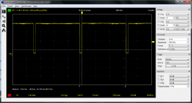
okay here is UB12 pin 18:
1666199355646.png

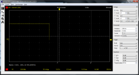
On pin 37 all I can see other than a flat line is this:

1666200223041.png

I also noticed there is a dead short between 37 and 38, not sure if that's normal (0 ohms resistance). The reason I noticed this is I tried to clip my scope lead onto pin 37 so I'd be free to mess with the settings on the PC without worrying about my hand holding the probe slipping but before powering it on I wanted to make sure the probe wasn't shorting the next pin over so I tested for continuity with my multimeter. After removing the probe there's still a short between these two pins.

On the schematic it looks like 37 is supposed to be IRQb and 38 is supposed to be IRQa?
 
So UB12 pin 18 is good.

You are now starting to get good traces - so well done.

I am still not convinced about your oscilloscope trace for pin 37. There looks like a signal is there - but I am not sure that your oscilloscope is set up to see it...

>>> On the schematic it looks like 37 is supposed to be IRQb and 38 is supposed to be IRQa?

Correct. In fact, if you follow the signal, you will observe it goes to all of the PIA and VIA devices. The /IRQ is an open collector signal (there is a pull-up resistor elsewhere) and any interrupting device just drags the signal LOW.

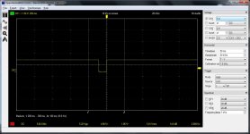
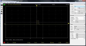
I am not sure why your timebase in post #195 (top trace) is 5 ms/div and in post #195 (bottom trace) is 500 ms/div. They should be the same (5 ms/div). Is the yellow arrow on the right-hand side the trigger threshold? if so, it is possibly too low on the lower trace.

Work at it a bit more and you will get it...

Dave
 
Okay I'll keep trying to find the signal on that pin. That's how much I had to change the timebase (to 500 ms/div) just to see anything other than a flat line. I also tried changing the triggering between normal, auto, single, etc... and moving the trigger arrow around to see if anything would show up even if it was jumping around.
 
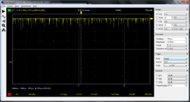
Okay this is what I was finally able to get off pin 37:
1666203301593.png
Notice though that to see that I had to bring the timebase all the way in to 100 us. This is the same as ub15 pin 21
 
What you are looking at there (at 100 us/div) is the noise that is present on all signals on a PET...

I would suggest getting a good trace from UB12 pin 18 (with the trigger level in the middle of the signal waveform and 1 V/div vertical) and then just move the probe over onto pin 37 and see what you get.

If nothing, make SMALL changes to the trigger level and shorten the timebase (make it slower) by a BIT. Don't go too mad with the controls...

Dave
 
Back
Top