• Please review our updated Terms and Rules here

NOT WORKING CBM 3032

Ok,

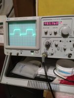
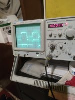
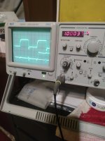
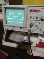
With the CPU/NOP generator removed, use your oscilloscope to check the signals SAn (see schematic http://www.zimmers.net/anonftp/pub/cbm/schematics/computers/pet/2001N/320349-7.gif) when F6 pin 1 is LOW.

You will have to trigger your oscilloscope on the channel that is monitoring F6 pin 1.

SA1 should be half the frequency of SA0 etc.

However, there is a bit of 'black magic' going on because each character in video memory is scanned multiple times (once per scanline).

Dave
 
Ok this is F6 pin 1:
 

Attachments

  • 1670343857645..jpg
    1670343857645..jpg
    1.2 MB · Views: 1
I am not sure you are measuring these as I suggested back in post #21.

You should be using two (2) probes with the oscilloscope in dual channel mode (with the trigger channel set to the channel that is measuring F6 pin 1).

Dave
 
I am not sure you are measuring these as I suggested back in post #21.

You should be using two (2) probes with the oscilloscope in dual channel mode (with the trigger channel set to the channel that is measuring F6 pin 1).

Dave
Ok this is F6 pin 12
 

Attachments

  • 1670351462637..jpg
    1670351462637..jpg
    1.2 MB · Views: 4
Getting there.

F6 pin 12 (SA0) is brilliant.

F6 pin 4 (SA1) could do with the timebase slowing down by one 'click'.

As we go up in SAx number, the frequency will get lower - so we need to compensate for this by slowing down the oscilloscope timebase to see the waveform.

You also need to see if you can get a stable waveform on the screen for the SAx signal you are measuring. This may just not be possible.

Remember, we are only interested in what is going on at the point in time when F6 pin 1 (the trigger) is LOW.

If you look at post #27 you should be able to see that when F6 pin 1 is LOW, that F6 pin 12 (SA0) alternates from LOW to HIGH and then back to LOW.

Post #28 just shows both a HIGH and LOW for F6 pin 4 (SA1) when F6 pin 1 is LOW. This indicates to me that the oscilloscope timebase is perhaps not adjusted correctly for the signal we are trying to measure.

Dave
 
Ok thanks... So again F6 pin 4
 

Attachments

  • 1670354457723..jpg
    1670354457723..jpg
    1.1 MB · Views: 2
i have always same waveform...i am desperate!!
Maybe i have bad videoram???
 
You can't have bad video RAM can you if you are measuring these signals ahead of it!

Just stop and think about what you are doing for a minute or two...

Dave
 
You can't have bad video RAM can you if you are measuring these signals ahead of it!

Just stop and think about what you are doing for a minute or two...

Dave
Need i change some Roms?
 
The ROMs have nothing to do with what we are measuring. This is a piece of pure TTL hardware.

Let's come back to this fresh tomorrow. I have shutdown my PC and checking schematics is a bit of a nightmare on a phone...

Dave
 
It is good that you have spotted that two pins (F6/4 and F5/9) have what appears to be the same signals on them. However, there is no need to get desperate and go off at a tangent. The reasons being:

1. You may have found a problem with the circuitry. In this case we need to investigate further and not give up!

2. We may have not understood how this circuitry works. In which case we still need to investigate to demonstrate that there isn't a problem - and this will increase our knowledge for the future.

Either way round, getting desperate and randomly going off and replacing video RAMs, ROMs etc. does not help. They MAY be at fault - but we don't have any evidence to support that so far. We have another PET thread where video RAMs are being randomly changed. With every change we get a different pattern on the screen - but I have no idea what is 'right' and what is 'wrong'. So, in my mind, this is not helping...

Right, enough said...

Let's measure the signals then at the input side of the video address multiplexers to see if we get the same thing as on the output. This is the 'logical' thing to do... If you get some 'strange' output from an IC, measure the input of the IC!

Use the same measuring technique (F6/1 as the trigger).

Measure the following pins (as the inputs to the video address multiplexers):

F6/14
F6/2
F5/11

Dave
 
Ok thanks!
F6 pin 14
 

Attachments

  • 1670432247225..jpg
    1670432247225..jpg
    1.2 MB · Views: 1
You are not adjusting your timebase are you to get the lower wave on the screen that we are trying to measure...

Dave
 
Back
Top