• Please review our updated Terms and Rules here

NOT WORKING CBM 3032

Yes, there is stuff there.

Have you downloaded the IC datasheet and worked out how the device works yet?

You have to be able to identify the function of the ICs in order to ascertain if they are working or not. Otherwise you are using your oscilloscope as a divining rod!

Dave
 
I am desperate because i can' understand how 74LS157 works :(
 

Attachments

  • Screenshot 2022-12-08 alle 11.40.34.png
    Screenshot 2022-12-08 alle 11.40.34.png
    108.3 KB · Views: 10
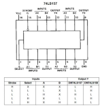
You need to break the truth table down into individual rows.

Each internal 'gate' (and there are four of them) have two inputs (labelled A and B) and one output (labelled Y). Delete the entire column for the '158 to save confusing yourself even more :)!

If the STROBE (G) input on pin 15 is HIGH, the output (Y) is always LOW. The other inputs (A, B and SELECT) are irrelevant (hence the X - meaning "don't care").

If you look at the PET schematic (http://www.zimmers.net/anonftp/pub/cbm/schematics/computers/pet/2001N/320349-7.gif) you should observe that the G pin (pin 15) is connected to 0V/GND/LOW - so the device is permanently ENABLED (and therefore the output Y always responds to the inputs A, B and SELECT).

With the SELECT pin (pin 1) LOW, the output (Y) responds to the A input.

With the SELECT pin (pin 1) HIGH, the output (Y) responds to the B input.

On the PET schematic, the SELECT pin (pin 1) is connected to CLK1 (which is a 1 MHz clock).

Therefore, when the clock is LOW, the Y outputs are connected to the A inputs and when the clock is HIGH, the Y outputs are connected to the B inputs.

For one half of the clock (LOW), the SAn signals are connected to the outputs from flip/flops and counters G6, F4 and F2 (A inputs to the '157).

For the other half of the clock (HIGH), the SAx signals are connected to the buffered address lines BAn (B inputs to the '157).

Can you follow my description with the logic table and pinout contained within the data sheet now?

As an exam question, can you work out what is wrong (from the datasheet pinout) on the PET schematic http://www.zimmers.net/anonftp/pub/cbm/schematics/computers/pet/2001N/320349-7.gif for IC F3?

Dave
 
Why do you assume that all of the '157s are faulty?

I have explained above how the device works. What don't you understand about my explanation? Take it a line at a time...

I assume you know how a 1 pole 2 way switch works?

Dave
 
Now I'm replacing the white socket of the cpu...I noticed that often the pins don't make good contact...if I move the cpu it freezes or the flashing characters increase....i am desperate for this!!
 
That appears to be a sensible approach. There is a 'cause and effect' rather than a guess.

Dave
That's right, I've learned this over time....I know these white sockets over time get faulty and no longer make good contact!
 
Nothing to do....cpu s' socket changed but i have always same situation....pettester stucked on the first screen and some flickering chars :(
 
Back to you trying to understand the '157 then...

You have to understand the individual components that comprise the IC's.

So, are you happy with the basic logic gates: AND, OR, NAND, NOR, XOR and inverters (including open collector outputs)?

Dave
 
I am afraid then that you need to do some research on logic gates and ICs before continuing. You have to be able to understand that what you are measuring is consistent with the functionality of the gate/IC.

Find some books in Italian on basic logic functions, or read up on the operation of the basic logic gates on the Internet.

Dave
 
NO. There is likely to be NOTHING WRONG with them until we prove otherwise...

If you don't know how they are supposed to work, how are you going to determine with your oscilloscope whether they are working correctly or not? If they are working correctly, there is no need to change them is there?

Read up on how logic gates of various types work. Start of with simple logic gates, then look at flip-flops, then counters and shift registers and then the 157 again.

Dave
Can i try to find a fault with logic probe maybe???
 
Back
Top