• Please review our updated Terms and Rules here

PDP 11/45, Part 4

You're right - VPC was a 16-bit quantity - so ignore my comment regarding 18/22 bits (I haven't quite woken up this morning)!

The D0XX diagnostics are fine (in fact - they are a good idea).

Dave
 
Hi All;

Dave, Thanks for the correction..
While You were posting I added another Question..

I have copied it into my NoteBook..
As, Bill would say -- Stand By..

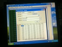
Here is a picture of the memory after it first is powered up..

001.jpg

THANK YOU Marty
 
Last edited:
Hi All;

Dave, I am very Surprised by the Results..

In PDPGUI I did an L 176, followed by an S..
And I got the following --
Address 200, Data 000176

I then pushed the HALT switch down, (Halted)..
and Pressed CONT
which showed the following --
Address '204 , Data 165212 (I kid you not), CONT,
Address '206 , Data 000176, CONT,
Address '210 , Data 000176, CONT,
Address '220 , Data 000574, CONT,
Address '222 , Data 000176, CONT,
Address '224 , Data 000176, CONT,
Address '226 , Data 000176, CONT,
Address '230 , Data 000176, CONT,
Address '000 , Data 000373..

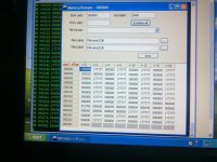
I then did a Memory Dump and here is the Picture --


002.jpg

I have a spare GRA Board that I can Substitute out, but that is it for spare working boards..

Also, Dave, Could You write a small snippet of a program that Displays the following -- "PASSED TEST xxx"" .. Where xxx is a number of passes, if not then just the Text.. And I can Insert it in place of where they ring the bell.. So, I know that the test passed.. Since I don't know how to make the 'ring the bell' work..

THANK YOU Marty
 
Last edited:
I get the impression that the CPU is working - it is the data display on the front panel lamps that isn't.

Question - what setting have you got the switch set for "BUS REGISTER", "DATA PATHS", "DISPLAY REGISTER" and "u ADRS FPP/CPU". If you have it in the wrong position - you won't see what you expect.

You can use PDP11GUI to initialise all of memory to zero. On the "memory window" right click and select "set all memory values to zero". You may also find the "fill every memory location with its address" useful as well. Don't forget that this modifies the memory 'copy' within PDP11GUI and you will need to do a "DEPOSIT ALL" to transfer to the actual 11/45 memory. See http://retrocmp.com/pdp-11/pdp-1144/my-pdp-1144/backplanes?id=75:pdp11gui-memory-window&catid=36.

You should be able to use this to 'zap' all the memory to 0 (HALT) beforehand if you like.

Don't forget there is also a "memory test window" in PDP11GUI (http://retrocmp.com/tools/pdp11gui/195-memory-test-window). It is a 'cheap and cheerful' test though...

It would be worth loading the address of each memory cell into it as a data pattern (using PDP11GUI) and examining some memory cells using the physical front panel to make sure that everything makes sense.

Deposit a HALT (0) and some NOPS into memory (240) and START the program running from the HALT address - it should HALT! You should then be able to single-step through the NOPS and see what you should expect on the physical console.

Don't forget to check the state of the "S INST/ S BUS CYCLE" and make sure it is set to "S INST" to single step a single 11/45 instruction at a time.

In the "PDP-11_Mainframe_Troubleshooting_Guide_Dec76.pdf" guide (page 25 of 122) it identifies the 'quiescent state' of the console.

Single stepping my program (and just following the address lights) it seems to work.

Try running it (without single stepping it) and see if it HALTs at the same address (ignore the first HALT instruction at address 176).

I have seen memory patterns of all 0's followed by all 1's before - so I wouldn't be too concerned unless examine/deposit fail to work as anticipated.

Dave
 
Hi All;

Dave, I was hoping to hear from you Again today..

"" I get the impression that the CPU is working - it is the data display on the front panel lamps that isn't. ""

I hadn't even thought of this, so Yes I will look into this..

"" Question - what setting have you got the switch set for "BUS REGISTER", "DATA PATHS", "DISPLAY REGISTER" and "u ADRS FPP/CPU". If you have it in the wrong position - you won't see what you expect. ""

I have it set to "DATA PATHS"..
And above that the other Switch I have "CONS PHY" but I can set it to "PROG PHY"..

"" You can use PDP11GUI to initialise all of memory to zero. On the "memory window" right click and select "set all memory values to zero". You may also find the "fill every memory location with its address" useful as well. Don't forget that this modifies the memory 'copy' within PDP11GUI and you will need to do a "DEPOSIT ALL" to transfer to the actual 11/45 memory. See http://retrocmp.com/pdp-11/pdp-1144/...indow&catid=36. ""

I think I found this window, I hadn't noticed it before..

"" You should be able to use this to 'zap' all the memory to 0 (HALT) beforehand if you like. ""

OK !!! I have Figured out How to do this..

"" Don't forget there is also a "memory test window" in PDP11GUI (http://retrocmp.com/tools/pdp11gui/1...ry-test-window). It is a 'cheap and cheerful' test though...

It would be worth loading the address of each memory cell into it as a data pattern (using PDP11GUI) and examining some memory cells using the physical front panel to make sure that everything makes sense. ""

OK !!!!! Will do.. I have done this and I looked at the Address locations from the front Panel and Verified them to be the same.. Just the first 200 or so locations..

"" Deposit a HALT (0) and some NOPS into memory (240) and START the program running from the HALT address - it should HALT! You should then be able to single-step through the NOPS and see what you should expect on the physical console. ""

OK.. I have left the Addresses in their respective location and then did the above.. Results in a minute..


!!!!!!!!!!!!!!!!!!!!!!!!!!!!!!!!!!!!!!!!!!!!!!!!!!!!!!!!!!!!!!!!!!!!!!!!!!!!!!!!!!!!!!!!!!!!!!!!!!!!!!!!!!!!!!!!!!!!!!!!!!!!!!!!!!!!!!!!!!!!!!!!!!!!!

I got some Interesting Results..

When I Set the Address from the Front Panel, and did a Start I get the following ---

before pressing start Load address '200
After pressing Start, the Address displayed shows '206 and DATA '200..

NOW, But
Doing the same thing in Console mode
L 200
S,..
I get Address (Displayed) '204 and Data '200 ..

So, Maybe my Start Flip-Flop is malfunctioning ?? Or something in that circuitry..

Now check this OUT.. Remember that I have put all '000000 in Addresses '200 thru 236..

I Press Load Address for '200,
I put the HALT switch down, and Press the Start switch.. And I get --
Address '200, Data '200, press CONT switch,
Address '202, Data '200, press CONT switch,
Address '204, Data '200, press CONT switch,
Address '206, Data '200, press CONT switch,
Address '210, Data '200, press CONT switch,
Address '212, Data '200, press CONT switch,
Address '214, Data '200, press CONT switch,
Address '216, Data '200, press CONT switch,
Address '220, Data '200, press CONT switch,
Address '222, Data '200, press CONT switch,
Address '224, Data '200, press CONT switch,
Address '226, Data '200, press CONT switch,
Address '230, Data '200, press CONT switch,
Address '232, Data '200, press CONT switch,
Address '234, Data '200, press CONT switch,
Address '236, Data '200, press CONT switch,
Address '240, Data '200, press CONT switch,
Address '200, Data '200, press CONT switch,
Address '202, Data '200, press CONT switch,
ETC.,,

!!!!!!!!!!!!!!!!!!!!!!!!!!!!!!!!!!!!!!!!!!!!!!!!!!!!!!!!!!!!!!!!!!!!!!!!!!!!!!!!!!!!!!!!!!!!!!!!!!!!!!!!!!!!!!!!!!!!!!!!!!!!!!!


"" Don't forget to check the state of the "S INST/ S BUS CYCLE" and make sure it is set to "S INST" to single step a single 11/45 instruction at a time. ""

IT is ..

"" In the "PDP-11_Mainframe_Troubleshooting_Guide_Dec76.pdf" guide (page 25 of 122) it identifies the 'quiescent state' of the console.

Single stepping my program (and just following the address lights) it seems to work.

Try running it (without single stepping it) and see if it HALTs at the same address (ignore the first HALT instruction at address 176). ""

???????????????????????????????????????????????????????????????????????????????????????????????????????????????????????????????????????????

I will now put Your Program in and Starting it in Console mode and see where it stops and report back to You.. I will start it at '200 in console mode..

Starting the Program at '200..
L 200
S..
The 11/45 front Panel shows the following --

Address '222, Data '200..

According to Posing #191 this is correct..
I then, changed Address Location '220 to '000002..

And I re-ran it starting from '200 , using the console front panel..

It Stopped it '216, which if the PC is advanced then that really is '214 which according to post #191 is Correct..

CORRECT ????

????????????????????????????????????????????????????????????????????????????????????????????????????????????????????????????????

"" I have seen memory patterns of all 0's followed by all 1's before - so I wouldn't be too concerned unless examine/deposit fail to work as anticipated. ""

I wasn't concerned, Just showing what state the Memory was in..

There's a bit here for me to do, and absorb, give me a few minutes to do and Implement each one..

THANK YOU Marty
 
Last edited:
I'm actually just at this same stage today with my 11/45 of trying various diagnostics with PDP11GUI...

One thing I've found very handy with the early "ring the bell" diagnostics -- track down the literal '000007' (ASCII BEL character) near the end of the diagnostic, and replace it with 000052 (ASCII '*') before you run the diagnostic. That way it will print a "*" to the terminal in PDP11GUI after each successful pass instead of trying to ring PDP11GUI's (silent) bell. You can do this directly in PDP11GUI's "Memory Loader" window, after "Load" but before "Deposit all".

The early diagnostics also display pass count in the 11/45 display register, so if you set your front panel to "DISPLAY REGISTER" you'll see it counting and cycling there if its working.
 
Last edited:
Hi All;

Fritzm, Thank You for the Very good Suggestions and Information..

I can do Both of those and see what kind of Results I get..

Please keep me informed about Your Progress and any more Suggestions !!

What all do You have with Your 11/45 ?? (Pictures welcome)..

THANK YOU Marty
 
What all do You have with Your 11/45 ??

So far what I've got mostly restored/working is an early 11/45 (serial #152) with memory management and floating point, DD11-D backplane extension, 128KW MS11-L, DL11-E console, and M9301-YB boostrap terminator. I say "mostly" because I've debugged enough of the CPU to pass simple diagnostics and run some toggled in programs, but haven't yet run any more comprehensive diagnostics so there may still be some bugs lurking in there (today!!)

Yet to be looked at are 2 RK05s w/ RK11-C controller and an LA-30P, so I still have a ways to go once the CPU is thoroughly debugged. I also have a nice VT52, but its down right now with a dead oscillator :-(

I've been blogging my restore at http://fritzm.github.io/category/pdp-11.html if anybody wants the full scoop or to see pictures, etc.
 
Oh, hmm, I'll look into fixing the feeds... The blog is a work in progress, based on the Pelican static renderer. It requires a fair amount of tedious munging around in Python to fix/add things, unfortunately. I am planning to stop by VCF-West -- it would be nice to meet some other folks in the community.
 
Hi All;

Fritzm, Thank You for the Information and the Link..

I Just followed Your link from the Last to the First..
I have also put Your Chaser Program into my NoteBook, I am going to try it out, when I finish writing this posting..

THANK YOU Marty
 
Hi Marty,

One note on the chaser program: the assembly listing starts at address 000000, but you probably shouldn't toggle it in there because best not to run on top of the trap vectors, etc. The program is relocatable; you can toggle it in at any working address range (001000 is always a popular choice).

Also, the delay on the chase is controlled by the front panel toggles. If you have them all down it will chase most slowly (because count down from zero wraps). Other than that, unless you have some of the most significant switches up, the chase may move too quickly to see, especially if you have an older '11 with incandescent bulbs in the panel instead of LEDs.
 
Hi All;

Fritzm, Thank You for the Information, as I have just tried it at '000000..

I will Relocate it..

But, so far, it doesn't seem to work, I get a blur of lights (leds) I have Leds in mine..

I have tried with all of the Switches down and all of them up..

NO change when I put the program in at '001000..

Also, do You have the Display switch at "DATA PATHS" or DISPLAY REGISTER" (I have tried both and it looks the same to me) ??

Also, Could You try the Putting in the Program that Dave Wrote in Post #191 and Please let me know of Your Results, both with switches and if You can with PDPGUI ??

THANK YOU !!!!

THANK YOU Marty
 
Hi Marty,

In the video attached to the blog, you can see the rate when I have switches 15 and 14 up, all others down. Display switch should be on DISPLAY REGISTER. I was running at address 100000 in my video because I hadn't repaired my MS11 at that point so my first 16K words of memory weren't working yet.

I'll give Dave's program a try next and let you know.
 
Hi All;

Fritzm, Thank You for giving Dave's Program a try..

I have switched to a different GRA Card and NO change.. It still isn't working correctly..

I need to find out Exactly where the Display Register is Located (which card) and what Controls it being Picked..

Since It looks the same to me when I have DATA PATHS or DISPLAY REGISTER displayed, I suspect that somewhere something isn't right..

THANK YOU Marty
 
Hi Marty,

Dave's program from post #191 works as expected on my 11/45, when toggled in from the front panel. I do note that the lights on the address display, when halted, are +2 from the addresses mentioned in the description there. That is, my address lights on the two halts read 222 and 216, respectively. I believe this is expected, since the PC will have already been incremented at the time of each halt.
 
Hi All;

Fritzm, THANK YOU, That is Exactly what I was hoping to Hear from You..

For Now, at least, I have You to compare Results with, on a real 11/45 to another real 11/45..

And You can expect the same from me, if / when I can be of any help to You.. Please don't Hesitate to ask..

Since trading out GRA Cards, I need to Re-Run that Program myself..

THANK YOU Marty
 
Hi Marty,

I know I'm jumping in late on this thread, but when I was debugging my CPU, I found the procedures in section 2.5 of the 11/45 maintenance manual (EK-1045-MM-007 over at bitsavers) extremely helpful. There's a careful sequence of tests to conduct from the front panel, including various short programs to toggle in, that check parts of the machine bit by bit and taking you up to the level where the first diagnostics should run. The info there can help steer you towards what cards and elements might be at fault.

You'll need a KM11 for some of it, but I think I recall you said you built yourself one on some earlier thread?

Maybe all or most of this already works on your machine, since you seem able to run the boot ROM which includes some basic diagnostics. But might be worth running through that section to see. Happy to try any other experiments or comparisons to help out -- just let me know!
 
Hi All;

Fritzm, Thank You for the information, I copied the Manual from Bitsavers, I am not sure If I have this one, I will have to take a closer look at it..
I have the KB11 Maintenance Manual (CPU)..

"" You'll need a KM11 for some of it, but I think I recall you said you built yourself one on some earlier thread? ""
Yes, but, I am not sure if it works at the present time.. I might spring for one like Yours..

Fritzm, I just am responding to Your Latest questions from Your Blog..

My Serial cards (M7800 and M7856) I have plugged into slots 26 thru 28 of the main MotherBoard..
I can Check what Pins I have what Power.. On my Notes, I have the following --
"" Slots 26 - 28 connect to P7 on + 5 Volts.. And Slot 15 +12 is tied to slots 26 - 28 for +12 volts.. "
I didn't say anything about -12 Volts, nor what pins these various voltages go to..
Also, Note that since I am using a PC Switcher Power supply, I am using + and -- 12 volts instead of + and - 15 volts..
I can trace this out if You need me to do so..

THANK YOU Marty
 
Last edited:
Hi Marty,

Thanks, I am very curious if you could measure voltage on pin CU1 on slots 26 thru 28. And if so, can you see wire(s) that deliver the voltage there from slot 15? Also, do you measure any voltage on pin CA1 on slots 26 thru 28?

Thanks much!
 
Back
Top