• Please review our updated Terms and Rules here

PET 4016 power in from transformer to Jumper 8

Dwight, thank you so much for your reply. most of this will require some research or advice on how to achieve these measurement with the scope. i will study it.

First thing to look at is the ripple frequency. If it is 60Hz, you have one bad diode. For ESR, you can look at the shape of the signal after the peak. There will be a curve on the up side and it will go over the peak. If after the peak, if follows a curved path before separating into a straighter discharge line, you'd know that it had poor ESR. If the voltage came up to about 11 or 12 volts and dropped to less than 6 volts between peaks, it would either mean the capacitance was really low ( dry inside ). If the voltage never makes it to 11 or so volts it might mean the load was too heavy.
Dwight

thank you! and a likely silly question, i can probe at any of the regulated outputs from the regulator section, such as the +3.7 that should be +5?

edit: after thinking about this, i should be probing the unregulated side?
 
Last edited:
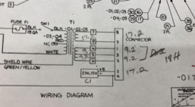
connector from transformer to J8:
1 2 3 4 5 6 7 8 9
brn red blk red brn blk key blue blue

2 and 4 go through the filter capacitor.

what i measure:
1 to 5 = 18 vac
8 to 9 = 17 vac

On my Pet with J8 cable not connected to main board (diode bridges), I get 22 VAC between J8- pin 1 to 5. You get 18 VAC. That is not much head room to develop the +/- 9 V unregulated from bridge circuit.
Also when J8 cable is connected to the board, you are reporting +7.5 VDC and -11 VDC unregulated instead of +/- 9 VDC. It should be balanced as the center tap (black wire) should be connected to J8 -pin 3 which is grounded to J8-pin6. Make sure the center tap connections are good.
 
for kicks, i pulled one of the monitor power wires from the transformer and re-read voltages. a few readings increased, notably 9-5 from 8v to 14v, 7-4 from 2.4 to 5.2, 8-6 from 4.8 to 7.8.

could this be normal? or is there possibly something shorted in the monitor section?

xformer voltages without motherboard or monitor power connected (in RED):
https://imgur.com/NOneS3B

Most of these reading are useless noise. With no loads and using a high impedance meter, most of these number are just capacitive coupling of the windings.
First thing to do is check to see which wires share the same winding. Disconnect the connector and with the power off measure the secondary windings with an ohm meter. The secondary winding should be less than 10 ohms. Note anything that looks wrong. The connector pins 8 to 9 should be less than 10 ohms. Pin 8 to to pin 1 should be open. Pins 1, 3 and 5 should be less than 10 ohms.
With the connector disconnected from the loads and powered up measure the voltage from connector pins 1 to 5. The reading you show looks wrong in the next post.
Dwight
 
The connector pins 8 to 9 should be less than 10 ohms. Pin 8 to to pin 1 should be open. Pins 1, 3 and 5 should be less than 10 ohms.
With the connector disconnected from the loads and powered up measure the voltage from connector pins 1 to 5. The reading you show looks wrong in the next post.
Dwight

i'm getting 0.4 ohms on 8/9, 1/3/5.

voltage 1 to 5 is 18.4.
 
What about the voltage reading from 1-3 and from 3-5?

Again, 18.4 Volts from 1-5 looks a little bit low?

Unfortunately, I had a tidy up over Christmas, and a key piece of paper (the transformer voltage readings from my system) have been stored away safely...

Dave
 
Last edited:
What about the voltage reading from 1-3 and from 3-5?

Again, 18.4 Volts from 1-5 looks a little bit low?

Unfortunately, I had a tidy up over Christmas, and a key piece of paper (the transformer voltage readings from my system) have been stored away safely...

Dave

Thanks for your input on my dilemma!

1-3 =9.2, 3-5 = 9.2, 1-5 = 18.4.
 
>>> It shows the center tap going to pin 4 and not pin 3.

Which takes me back to my post #2 where something 'needled' me about pin 4...

I need to find my bit of paper that had all of this on...

I think pin s3 and pin 4 are swapped in some diagrams - either that or some PETs used pin 4 for the centre tap and others used pin 3...

>>> 1-3 =9.2, 3-5 = 9.2, 1-5 = 18.4.

So, you have Volts there - and both halves of the winding look OK.

Dave
 
I have just had a look at my PET.

The centre tap goes to pin 3 on J8.

Pin 4 on J8 has a red wire which goes to the capacitor positive terminal (as does J8 pin 2).

Pins 1 and 5 on J8 should have brown wires - these are the two ends of the double winding; and pin 3 of J8 should have a black wire - which is the centre tap.

J8 pin 4 is the positive output from the bridge rectifier 'going to' the capacitor which then 'comes back in' on J8 pin 2 to the +5V regulator.

It's getting a bit late in the UK, so I will measure my transformer voltages tomorrow - but Dave has posted his and your ac voltages look a little bit low when compared to his (18.4 Volts on yours and 22 Volts on his).

Dave
 
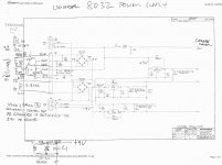
The schematic on Zimmers shows different pins on connector 8. I'm using the schematic that ( I think it was ) Dave_m posted.
It shows the center tap going to pin 4 and not pin 3.
See http://www.zimmers.net/anonftp/pub/cbm/schematics/computers/pet/univ2/8032087-11.gif
Note when we were talking about a floating center tap?

No, The center tap from the transformer is a black wire and goes to the negative terminal on the big C1 capacitor. From there, two black wires go to J8 pins 3 and 6. Both are grounded on the mainboard.

J8 pins 2 and 4 are red wires that go to the positive terminal of C1, The voltage there is the unregulated +9 VDC.

-Dave
 
Hi Dave_m
Thanks for the clarification. The wiring makes sense now. I didn't look at the way they'd used the diode bridge.
Dwight
 
xformersmall Webp.net-resizeimage.png

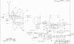
for reference, my readings (the image size restrictions on this forum are harsh).

so, where should i go next with this?
 
Please tell me you haven't got 17.2 Volts across J8 pins 2 and 6 though!!!

Ah, found my paperwork! I had put it somewhere safe after all!

I read approximately 8V AC from the centre tap (black wire) to each of the brown wires; and approximately 16.3V AC between the two brown wires. So I read less than yours (with no load).

It's all coming back to me now! J8 pin 4 is missing from the schematic in post #39 - which is why it is difficult to see how things work when you marry up the transformer/capacitor/J8 schematic with the main board regulator schematic. There is a wire missing from the schematic!

Dave
 
Last edited:
Connect things up again and remeasure. Make sure when doing DC measurements that the meter is set to DC.
Those reading that you have look correct.
Dwight
 
Back
Top