• Please review our updated Terms and Rules here

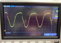
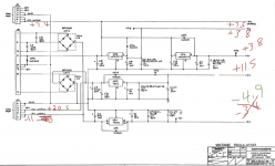
PET 4016 power in from transformer to Jumper 8

That is a lot of ripple. It is way too much. That is why I asked you to check it at the large capacitor. Use the negative post of the capacitor as your ground. There are two possibilities for that much ripple. One is the capacitor has dried out or that there is a heavy load of the power supply. Since you have a new capacitor coming in, it may solve the problem. If it is a load issue, it looks to be on the +5V outputs as you can see on the curve where the regulators kick in. I think it looks like the large capacitor as it drops way to fast below that.
Dwight
 
It's alive!!!

It's alive!!!

my 23000 mf cap arrived today. i measure it with my ESR meter and was getting a reading of .017 vs the original showing OL. I popped it in, turned the PET on, and heard the proper chirp startup that was different than the partial piezo squeaks i had been hearing.

I plugged in the monitor, and BAM!!! It is ALIVE!!!

https://imgur.com/QDydFEZ

I'm not done chewing you guys' ears on this. And I want to sincerely thank all of you for your patience and methodical advice in pointing me in the right direction. Dave's things to look at included this cap.

Wow. Now to clean things up and test the keyboard.
 
That is a lot of ripple. It is way too much. That is why I asked you to check it at the large capacitor. Use the negative post of the capacitor as your ground. There are two possibilities for that much ripple. One is the capacitor has dried out or that there is a heavy load of the power supply. Since you have a new capacitor coming in, it may solve the problem. If it is a load issue, it looks to be on the +5V outputs as you can see on the curve where the regulators kick in. I think it looks like the large capacitor as it drops way to fast below that.
Dwight

Thanks, Dwight, I was probably typing as you posted this. I truly want to understand how you read this so well from the scope. you were bang on!
 
Thanks, Dwight, I was probably typing as you posted this. I truly want to understand how you read this so well from the scope. you were bang on!

Measure the ripple with a good capacitor and you'll see why I was so sure it was a bad capacitor. Post the picture so that we can have it for others to see. Use the advance edit to get the picture attached to the MB here, instead of some remote storage that may go away in a year or two. We tend to lose a lot of good reference pictures using remove storage.
Dwight
 
Sweet that it is fixed now!

Yes, at 2 Volts/division the capacitor may as well not have been there. Oh, it wasn’t :)!

Have you tried saving and loading programs yet?

Dave
 
i've only typed a HELLO WORLD program on it so far. I do have an untested 4040 drive unit that i got with this pet and the cable for that arrived earlier this week. so that will be on the agenda very soon.

I'll clean up my work and attempt to document they key learnings in forum-hosted images as Dwight suggested. The image size limits with this forum are cumbersome and I need to streamline my resizing process. I will do that today or tomorrow.

The new scope reading on pin 6 of J11 (NOT J12 as i mistyped above) looks much different and the auto view on my scope now defaults to 200mv divisions.

Also I am now getting +5 and -5 instead of +3.8/-3.8 out.

Again, I sincerely thank all of you for your help. I'll document this issue and resolution in a followup post in this thread this weekend.
 
Summary of this problem and fix:

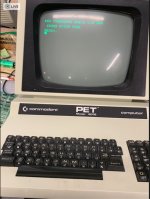
Distorted video output, garbage characters, partial distorted piezo beeps, low voltages.
z pet bad screen C PET Screen Shot 2020-02-15 at 2.57.52 PM.jpg

9 and 5 volts DC too low.
rsz_pet_voltage.png

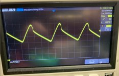
oscilloscope measurement at pin 6 of J11 with original C1 23000 mfd filter capacitor.
z pet ripple old cap pet scope  +9 unreg.jpg

oscilloscope measurement at pin 6 of J11 with replacement C1 23000 mfd filter capacitor.
z pet ripple new cap Screen Shot 2020-02-22 at 2.06.13 PM.jpg

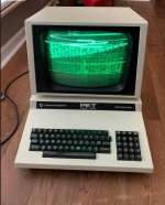
the PET lives! correct voltages and video.
pet lives Screen Shot 2020-02-22 at 1.09.04 PM.jpg

Summary: replaced C1 filter capacitor.
 
When you look at the second plot of the ripple, the first thing to notice is that the peak to peak is about 600 mv. Again, it is important to note the frequency. 60 Hz on a full wave rectification indicates an open diode.The next thing to notice is the tight shape of the wave. On the up swing, we are seeing the line following the input sine
wave. Just after the peak we see the shape break away form the sine path to a relatively constant slop until the sine wave peak catches up to it.
Now, looking at the first picture. Notice the shape is kind of following the sine wave but is clipping on something on the up sing. This is likely the regulators getting enough voltage to start conducting. Notice that the wave form goes almost all the way to zero. We are probably seeing the tiny effect of the 1 uF caps on the inputs to the regulators, keeping it from going all the way to zero. Even a shorted +5V would not track all the way down to zero as the regulators would stop conducting earlier. To be a load problem it would likely nee to be before the regulators, on the raw DC side. Since you were not complaining about a hot transformer, that leaves only a capacitive failure. As a dry capacitor would cause this wave form.
It is important to diagnose problems rather than doing random replacements. Although, you may hit on the source of the problem, even in a shorter amount of time. There are many cases were more damage was done by needless replacements and the the system has one or more new problems that need to be fixed. We often heard of the successful easter egg hunts but rarely the failed ones. These just end up on ebay for someone else to fix.
Dwight
 
When you look at the second plot of the ripple, the first thing to notice is that the peak to peak is about 600 mv. Again, it is important to note the frequency. 60 Hz on a full wave rectification indicates an open diode.The next thing to notice is the tight shape of the wave. On the up swing, we are seeing the line following the input sine
wave. Just after the peak we see the shape break away form the sine path to a relatively constant slop until the sine wave peak catches up to it.
Now, looking at the first picture. Notice the shape is kind of following the sine wave but is clipping on something on the up sing. This is likely the regulators getting enough voltage to start conducting. Notice that the wave form goes almost all the way to zero. We are probably seeing the tiny effect of the 1 uF caps on the inputs to the regulators, keeping it from going all the way to zero. Even a shorted +5V would not track all the way down to zero as the regulators would stop conducting earlier. To be a load problem it would likely nee to be before the regulators, on the raw DC side. Since you were not complaining about a hot transformer, that leaves only a capacitive failure. As a dry capacitor would cause this wave form.

Thanks, Dwight. Very clear explanation.
 
Dokken,
You did a good job on your computer.

I have a few questions. Was there no goo leaking out of the old capacitor? Or did capacitor dry out as Dwight mentioned? Is the replacement capacitor about the same size as the original? How did you attach it to the chassis?
 
Dokken,
You did a good job on your computer.

I have a few questions. Was there no goo leaking out of the old capacitor? Or did capacitor dry out as Dwight mentioned? Is the replacement capacitor about the same size as the original? How did you attach it to the chassis?

No leaks, no bulging. So I'm assuming it dried out. The replacement is similar in size and I zip tied it to the chassis using zip ties iike the original.
 
OK, thanks to the forum team I learned something about power supplies from this problem. With no goo, I would have replaced the diode bridge and wasted time and effort with that first.
 
OK, thanks to the forum team I learned something about power supplies from this problem. With no goo, I would have replaced the diode bridge and wasted time and effort with that first.

Yeah, excellent 'Linear Supplies 101' from Dwight.

Maybe just my own experience but unlike modern small caps I've never seen goo coming out of one of those huge old large-value caps but I have seen them partially or completely open internally (just had a PET with that issue as a matter of fact). Checking ripple with multimeter on DC line but set to AC volts both with and without load can be a simple but revealing test, as can checking ripple frequency as Dwight suggested.
 
I just opened the 4040 drive case for the first time. Two more of those 23k uf caps. ughhh.

I have a broken drive door latch. Any pointers to parts to search for such as brand of OE drive? or I can probably repair this one, but just curious.

z pet drive door Screen Shot 2020-02-24 at 4.02.16 PM.jpg
 
I used a brass rod and some super glue/baking soda and the door works great.

a pet door 1 Screen Shot 2020-02-26 at 4.18.04 PM.png

a pet door 2 Screen Shot 2020-02-26 at 4.18.48 PM.png
 
Back
Top