• Please review our updated Terms and Rules here

PET 8032 display issue

Robin Elvin

Member
Joined
Feb 13, 2022
Messages
24
Location
Wigan, UK
Hi,

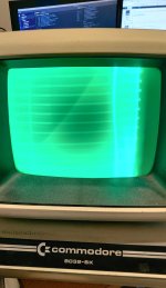
I'm wondering if some PET experts can guide me through diagnosing and repairing a PET 8032 I am trying to fix. When I got the machine it was completely dead which I quickly discovered was due to no 5V supply. That turned out to be caused by both 5V regulators having failed so I replaced them and got the familiar chirp. Now I have no display on the screen except excessive flyback lines. I hooked another PET CRT up to check and it shows the same.

Not being familiar with the PET I have studied the schematics relating to the display and the only thing which I can see that looks possibly wrong to me is RA4 on the 6845 CRT controller seems to have no activity. Since this looks to be OR'd with RA3 to produce 'NO ROW' I would expect something on that pin. I lifted the leg on the CRTC in case something was pulling it low and checked again but there is nothing coming from it. Although, as I said, I'm not familiar with the PET so not sure if this is expected.

Other outputs on the CRTC seem to be ok including vertical drive at 50Hz and horizontal drive at 20kHz and verified at J7. There appears to be a regular 20kHz signal on the video pin 1 of J7 also.

Any help appreciated and I look forward to learning more about the PET.

Thanks
 
Hi Robin. I'll be passing your house tomorrow on the M6 on my way up to sunny Lancaster...

As this is your first post, welcome to VCFED. Be aware that you will be under moderation for your first 10 posts.

Can you post a picture of the screen please?

This sounds like a 'strange' fault - but the photograph would help big time.

Dave
Hi Dave,

Be sure to wave as you go past!

I've attached an image of the screen. Adjusting the brightness doesn't seem to have much effect. Apologies for the quality of the picture - I can't seem to get my phone to take a decent picture without lots of flicker.

PET fault.jpg

Robin
 
Last edited:
The VDU is possibly being fed with abnormal signals from the computer main board, unless there is a fault in the VDU, but basically since the VDU, to display a scanning raster at all, at least requires H and V drive signals, probably these are both present, but not likely normal as the raster is folded over on itself on the right which could happen if the H drive frequency was incorrect. But the video drive, contains no information and is stuck. But overall, with this sort of raster image with uncontrolled brightness, the CRT bias is way off, I am more suspicious of the fault being in the VDU, than the computer board.

The best move initially at least would be to put the scope on the H drive and the V drive and the video drive signals on the VDU's connector, to see if they look basically normal, or not.

I'm not sure what VDU is in the 8032, if you could post a link to the Zimmers schematic I might be able to suggest where to make checks in the VDU, especially if the drive signals from the computer board are normal.
 
I have 50Hz on the vertical drive and 20kHz on the horizontal drive and video pin - no idea if that's correct. I have also plugged into another working PET CRT and I get the same problem. I should try the working PET on this CRT to make sure it does actually work. Will do that later.

Here's the link to the Zimmers page with all the schematics: http://www.zimmers.net/anonftp/pub/cbm/schematics/computers/pet/8032/index.html
 
It would be worth double-checking whether the board you have physically fitted is an 8032, a Universal or a Universal 2. They do vary a little bit. With Commodore being Commodore - you may have a later 8032 fitted with a slightly different card. Or it may have been 'repaired' at some time in the past with an exchange board.

Either way round, if you check the Technical Manual at the bottom of the page you linked to - you will see the exact waveform for the horizontal and vertical monitor drive signal that you should be observing - not only frequency, but pulse duration as well.

Dave
 
The chirp is promising. If you have video sync signals at the right frequencies, that means the CRTC has been initialized.
Often times bad RAM, or flaky Kernal or Edit ROM will boot far enough to init the CRTC, but crash before getting to basic.
If you power cycle quickly after the CRT is warmed up, do you see any characters on screen?
If you have a datasette, with it connected, does the motor start and stop when you press play? That would indicate that the CPU is running and servicing interrupts.
You can also try starting with the character ROM removed. That should give you an all white (green) screen instead of black.
 
It would be worth double-checking whether the board you have physically fitted is an 8032, a Universal or a Universal 2. They do vary a little bit. With Commodore being Commodore - you may have a later 8032 fitted with a slightly different card. Or it may have been 'repaired' at some time in the past with an exchange board.

Either way round, if you check the Technical Manual at the bottom of the page you linked to - you will see the exact waveform for the horizontal and vertical monitor drive signal that you should be observing - not only frequency, but pulse duration as well.

Dave
The board is marked "ASSY NO 8032030"
 
I have 50Hz on the vertical drive and 20kHz on the horizontal drive and video pin - no idea if that's correct. I have also plugged into another working PET CRT and I get the same problem. I should try the working PET on this CRT to make sure it does actually work. Will do that later.

Here's the link to the Zimmers page with all the schematics: http://www.zimmers.net/anonftp/pub/cbm/schematics/computers/pet/8032/index.html
That would pretty well confirm the problem is not in your PET VDU, but the signals coming from the computer board. You could double check that as you suggest, by feeding your VDU from another known working PET to double check that the VDU is ok. Sometimes, there can be more than one problem happening.

If this is the case, as Daver2 says, you will need to examine the three signals coming from the computer on the scope, to check them, to see if the duty cycle is correct. I'm guessing that probably the H & V signals are ok but the video signal is defective. The video signal should only be high when there is screen text/graphic data displayed, so most of the time it should be low when you look with the scope, unless say the entire screen was filled with text/symbols, but we can see that is not the case. Probably it is stuck high most of the time.
 
Last edited:
That would pretty well confirm the problem is not in your PET VDU, but the signals coming from the computer board. You could double check that as you suggest, by feeding your VDU from another known working PET to double check that the VDU is ok. Sometimes, there can be more than one problem happening.

If this is the case, as Daver2 says, you will need to examine the three signals coming from the computer on the scope, to check them, to see if the duty cycle is correct. I'm guessing that probably the H & V signals are ok but the video signal is defective. The video signal should only be high when there is screen text/graphic data displayed, so most of the time it should be low when you look with the scope, unless say the entire screen was filled with text/symbols, but we can see that is not the case. Probably it is stuck high most of the time.
Thank you, Hugo. It looks like there might be 2 problems. If I connect the working PET board to this VDU I get the same issue but I can also see a blurry image in the noise - not good enough to make out what it is but it confirms that it is trying to display something. With the faulty PET connected I see no image changes even when typing lots of garbage.

You were right about the VDU so I will first try to fix it so I get a cleaner blank image and then go back to fault-finding the main board. I'll also try removing the character ROM to what I get.
 
The key gate is on schematic http://www.zimmers.net/anonftp/pub/cbm/schematics/computers/pet/8032/8032029-08.gif UD4 pins 1, 2, 12 and 12.

Pin 1 is the video signal itself.

Pin 2 is NO ROW from the CRTC.

Pin 13 is a delayed version of DISP ENA from the CRTC.

Some of the outputs from the CRTC could be faulty (didn't you already identify a potential issue with the NO ROW signal previously?).

Alternatively, the D-type delay flip-flops could be misbehaving somewhere and always outputting a logic '1' (erroneously).

Dave
 
The usual things to check on the VDU, the 18V power supply voltage is correct out of the regulator with no ripple. Check the negative voltage that is used in the CRT''s grid circuit provided by D754, and check the + power supply rail E30. If either of these fails the CRT beam current & brightness goes up very high. The E30 voltage comes via a diode and series resistor from the LOPT, sometimes the resistor (R751) goes open if there is too much current say from a leaky electrolytic cap.

If the power supplies are ok, then check the output of the video amplifier on the scope (emitter Q222) this should be at around +30V most of the time and only go low when some text or graphic information comes along when the video input (test point 1) goes logic high. (As you can see with the video amplifier chain,it inverts the signal 3 times, so overall it is an inverting amplifier)

Those component references relate to this schematic;

 
Last edited:
I've just managed to find 5 minutes to look at the VDU. Once I got the cover off I noticed I had this board layout:


And so this is the schematic


I took the VDU board out and inspected it. The board was black around CR2 and on closer inspection this looks to have been replaced with some board trace repair. It checked out OK as did all the other diodes on the board. Input voltages were good and there was 18V from VR2. Not having any other obvious thing to check I turned one of the pots which was now accessible and the picture was now clear and visible! The whole screen was now filled with bars and there was a flashing block where the cursor was. I typed a few characters and the cursor moved but every character displayed the same horizontal block. SHIFT+CLR/HOME did not update the screen but the cursor did move to the top left.

So this looks like the character ROM is broken or not being accessed correctly. When I look at the board I have 5 ROMs :-

901465-22 (Kernal)
901474-04 (Editor for business keyboards)
901465-20 + 901465-23 (Basic 4)
901465-21 on EPROM (Basic 4)

Character ROM should be in UA3 but there is nothing there which explains a lot. No problem, I can use my TL-866II for the first time. I had also bought some 2532 EPROMS just in case. Never having done this before I hadn't realised the programmer only outputs a program voltage of 18V and the chips require 25V so I will have to think of another way to make a new character ROM.
 
I burned a new character ROM and now looks like the display RAM is faulty. I'm getting 2 issues; only valid characters in every odd column (even columns display garbage) and the even columns have a different issue in the top half to the bottom half. In the top half of the screen the even columns are changing rapidly almost like static in each cell. In the bottom half the even columns are displaying a PETSCII graphic symbol and when I type over them they change to various different symbols. I haven't checked the character codes but it looks like stuck bits. Two out of the 4 chips are getting a lot hotter than the others.

Anyway, I have ordered some static RAM and I will update when I've replaced it.
 
Next update. I removed the video RAM, added sockets and put the existing chips back to make sure everything was the same. It was so I replaced the first chip and powered up and the display was slightly better. I then decied to replace all the remaining 3 chips and powered up and .... nothing. I heard the chirp but no display. An hour of pulling chips, tweaking the monitor and pulling my hair out ensued until by chance I touched the cable which goes to the monitor and the display briefly appeared. It turns out this cable has a break in it so that's another job to add to the list!

Anyway, replacing the RAM chips hasn't quite fixed the problem. Whilst I can now see the BASIC banner and ready prompt I still have some garbage in the lower right quadrant and then after a while the screen then fills with random characters very rapidly. I'll pick this up again when I next get some spare time.
 
Yep, my PETTESTER EPROM that replaces the EDIT ROM in the PET. I will post a link to it presently. Please read the documentation first...

Dave
 
Back
Top