daver2
10k Member
I assume there is still no activity on the processors /IRQ signal then?
Dave
Dave

Dave, thank you for your continued help! Yes, UB12 pin 9 is HIGH.First off, DIAG is wired to UB12 pin 9 (PA7) and it is also wired to the sounder logic. I wonder if both problems are connected?
Anyhow, measure the logic level of UB12 pin 9. It should be HIGH.
Reset button is wired up. If the Tynemouth board is simulating both RAM and ROM, it goes directly to the monitor (shown previously), as in the photo below.Secondly, I would suggest fitting a reset button (a normally open pushbutton) between pins 1 and 2 of UD16 (the reset NE555 timer). Power up the PET, start video recording the screen and press/release the reset button. The video will capture the tests as they run. Unfortunately, the delay between tests is fairly short in version 4 of my firmware. It is much longer in version 5. The first test should output all of the video characters to the screen and read them back. Check on the video that they all look correct. The test firmware verifies that it can correctly readback the values that were written - but that is still no indication that they all appear correctly. I don't think you will have a problem - but it always pays to check.


The RAM test that is failing attempts to write $00 into address $0000, $01 into address $0001, ..., $FF into address $00FF and then reads the value back. It repeats this test for page 1 ($00 to address $0100, ..., $FF to address $01FF). A 'good' test is represented by a 'g' character. A 'bad' test is represented by a 'b' character. The 'bad' character that was read is then displayed instead of a '.'.
What this tells be is that the only memory cell in page 0 ($0000 to $00FF) that is working is address $0000. All of the other addresses ($0001 to $00FF) all return $00 (character '@'). In page 1 ($0100 to $01FF) the only memory cell that is working is address $0101. All other addresses return $01 (character 'a'). Let me think about how this pattern could be manifest...
With the Tynemouth card simulating the RAM - I am assuming my test program is identifying the ROM checksums correctly. What happens if you press the keyboard keys (one at a time) when the ROM checksums are being displayed? You should observe a single '1' bit being set in the KEYBOARD keymap on the test screen.
Dave
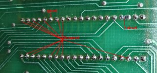
Apart from defective soldering, it is always possible that the socket itself is damaged and has lost spring tension on one or more of its pins and has a defective connection.Thanks Dave.
Removing the keyboard connector makes no difference. Still all FF's.
That PIA works fine in my good 8032, so it almost has to be something with the socket, which I installed. I'm usually pretty confident of my soldering, but I certainly could have made a mistake. I'll start tracing all that out next. That will have to be tomorrow. That's all I had time for today.
You are correct, this PIA chip is initialized to generate an interrupt request (/IRQ) on pin 37 when it sees a high transition on its CB1 input (pin 18). The interrupt handler routine then scans the keyboard and blinks the cursor among other tasks.It is interesting that the missing cursor effect is also caused by the keyboard PIA IC being absent from its socket.
Ok, so I checked the input power on UB12 pins 1 and 20, measured directly on the IC, and I get a perfect 5.03v.Apart from defective soldering, it is always possible that the socket itself is damaged and has lost spring tension on one or more of its pins and has a defective connection.
It is interesting that the missing cursor effect is also caused by the keyboard PIA IC being absent from its socket. Since your PIA IC is ok in your other computer, but not in this one, perhaps it is not being powered properly and acting like its "not there". So the best thing to do initially is to check the power supply & ground pins on the actual IC body, with the meter.
")

I don't have the schematic handy, but there is a small trap to fall into when examining TTL's IC's with open collector outputs, like the 7417 and deciding if they might be defective. There will appear to be no output, if the pullup system (often a resistor but sometimes it can be another IC's input pin current) on the output of the buffer has failed. So if the output is sitting low, it is always worth stringing the output via a 1k resistor or similar to +5v, to see if the buffer is actually working.Ok, now THIS is interesting. There's NO 02 clock signal on Pin 25 UB12 or UB15. It goes into Pin 1 of UD15 from the CPU, but doesn't come out. I have dozens of different TTL chips here. Do you think I'd have a 7417? Of course not! Gonna have to order. I'd hate to pull one from a working machine.
Understood. In fact, I think I learned that at the beginning of this very project about the behavior of open collector outputs. Anyway, the Pullup is good, but there's no signal at the output.I don't have the schematic handy, but there is a small trap to fall into when examining TTL's IC's with open collector outputs, like the 7417 and deciding if they might be defective. There will appear to be no output, if the pullup system (often a resistor but sometimes it can be another IC's input pin current) on the output of the buffer has failed. So if the output is sitting low, it is always worth stringing the output via a 1k resistor or similar to +5v, to see if the buffer is actually working.
Great progress !Understood. In fact, I think I learned that at the beginning of this very project about the behavior of open collector outputs. Anyway, the Pullup is good, but there's no signal at the output.
So I substituted a 7407, which looks like it should work, and for the first time ever I have a cursor and the keyboard works! That's WITH the Tynemouth board installed and the RAM switched in. Looking like I've definitely still got bad RAM.
Thanks. Couldn't do these repairs without you folks. I have basic troubleshooting skills, but talking to people who know what the various circuits should be doing and when is invaluable.Great progress !
Interesting. I'll have to read up on this. I have to imagine I've got RAM bad in the lower 16K. Which IS the lower 16K anyway? I'm not even sure. I'm sure the information is out there somewhere, but I don't know it offhand.I made a system to check the dynamic RAMs in the Dynamic PET. The ROM plugs into a spare socket and a "hardware Adapter" dynamically disables the lower 1k or 2k of Dram and substitutes in SRAM.
The ROM program (in the article) might be of some use as it has three programs operating in the high cassette buffer area (moved there from a 4th ROM program), that are useful for diagnosing individual defective DRAM IC's, they write checkerboard patterns and any any value byte you want to the whole memory from 0400h to 7FFFh in the 32k PET.. Though it was intended to help when the DRAMs are soldered in, so that only defective ones end up getting un-soldered. Though you can just do it with POKEs & PEEKs, but it is better to check nearly all the memory.
One thing (though I'm not sure about this for your PET model's RAM setup) since all of the DRAM's are only 1 bit (in the case of my PET at least) every one of them contributes to the Byte value. If one IC in the lower 16k is defective (non responsive or output stuck) the computer cannot boot and a black screen results. If one of the IC's in the upper bank is defective, in the case of being non responsive the computer will boot and report half the expected RAM amount, or if the output is stuck it inhibits the IC in the same column in the lower bank and again it won't boot.
By inspecting the values of the returned bytes (provided another memory is supporting the OS) it is fairly easy to figure out which particular DRAM IC's are defective.
www.worldphaco.com/uploads/DRAM%20MEMORY%20TEST%20SYSTEM%20FOR%20THE%20DYNAMIC%20PET%20COMPUTER.pdf