• Please review our updated Terms and Rules here

PET 8032 Video to MDA Monitor

I've pondered this several times myself since I started fixing up all my stored PETs back in October. There's several mono monitors in my collection so it would be great if I could just make up a cable to connect an 8032 to say Apple][ or Sanyo MBC555 monitor.

I found a home-made TV-out converter in a box of PET bits in the garage recently, haven't plugged it in yet...

Cheers

The PET video signals are 5V TTL. Make sure there is a voltage divider in the adapter to attenuate the PET composite signal to about 1V if you are not sure about the input level capability of the monitors.
 
I guess it'll only become important as the original tubes die with age. Fortunately so far I've only had one dead one and that's because the previous owner managed to damage the neck so that one's toast which is why I was looking at this thread in the first place.

I plugged in the TV adapter tonight since I had an 8032 board next to an old colour TV in the kitchen (it was testing the -SK monitor) and it looks like it originally came with my blue 2001-8 since the signal is all out of whack on an 8032. I even fished out an old 70s B&W TV from the garage which has separate H&V controls and the picture looks very like the one I get on my scope.

I'll start a new thread for it.

W
 
Well ntsc lcds with composite are plentiful and a simple editor rom replacement would be pretty easy for quick testing.

In my experience, composite inputs on LCD monitors and TVs are useless for anything except real TV/video. If it also has a VGA input, you might be a bit more lucky (it makes it more likely that there's some engineering inside that will at least make an attempt to sync to various H/V frequencies) but in general, most LCD screens I've seen will just throw their hands up in the air if they get anything remotely non-standard. A non-interlaced NTSC/PAL signal? "No Signal". Horizontal or vertical frequency slightly off? "No Signal".

That's why I'll probably always keep just a few CRTs around for hobby projects: One decent 17" flat screen Sony Trinitron SVGA monitor that's way too heavy to get from the garage, but it goes up to 1600x1200. One professional 13" PAL/NTSC monitor with amazing picture quality that someone got me at a university auction for less than a dollar. A smaller 5" NTSC color monitor with lots of controls including H/V sync and H/V size that I got for free, and one tiny 5" black and white TV with audio/video inputs that I got at the Goodwill store that's super easy to carry around.

===Jac
 
For my Commodore PET main board Tester, I'm looking at hooking up the 8032 PET video (80 column X 25 lines) to an external monitor. I tried composite video to an old Sony Watchman TV, but the Sony could not sync the the PET. I think the older 40 column PETS are closer to the TV bandwidth, but the the 8032 has a higher Horizontal rate. I was wondering if anyone has had success using an old PC Monochrome monitor. The PET has TTL level Horizontal, Vertical and video signals. The frequencies are 20 KHz and 60 Hz vs the MDA spec of 23 KHz and 50 Hz. Is this close enough?

Dave,

did you find a way to connect MDA monitors to the 8032 board? I did a try connecting it directy (h-sinc, v-sinc, video and gnd) but I only got an horizontally flickering and distorted white noise (it probably was the boot screen).
 
Dave,

did you find a way to connect MDA monitors to the 8032 board? I did a try connecting it directy (h-sinc, v-sinc, video and gnd) but I only got an horizontally flickering and distorted white noise (it probably was the boot screen).

Hi Giovi,
No, not really. The best solution is to use one of Steve Gray's modified EDIT ROMs to change the parameters to the 6545 CRTC chip to match the standard NSTL TV standard. Here is a blurb from his webpage. See Screen Refresh Option #3:

Screen Refresh


Early PET machines had no CRTC controller chip and generated a FIXED screen refresh of 15kHz (approx) on its internal 9" monitor. The signal could be sent to an external NTSC video monitor. Later PET/CBM's added the CRTC controller which allowed the video signal to be configured on the fly. The refresh was set to 20kHz for the new 12" screens. Unfortunately this meant the signal was incompatible with external monitors. Luckily the CRTC controller settings can be adjusted.


Setting the REFRESH option allows you to select the proper CRTC register values for your intended monitor. The following are available:


NUM LAYOUT
COLSxROWS V-FREQ H-FREQ SCREEN INVER NOTES
0 40/80x25 50 20.000 Internal 12" YES European 4000/8000/8296/9000
1 40/80x25 60 20.000 Internal 12" YES North America 4000/8000/8296/9000
2 40/80x25 50 15.625 External PAL YES PAL monitor
3 40/80x2 60 15.748 External NTSC YES NTSC monitor
4 40/80x25 60 15.748 Internal 9" NO Old PET 9"
82 40/80x25 50 16.949 Internal 12" YES 8296D only!
83 40/80x25 50 16.949 Internal 12" YES 8296D only!
90 40/80x32 60 ? Internal 12" YES 8296/8296D machines only!
91 40/80x35 60 ? Internal 12" YES 8296/8296D machines only!
92 45/90x35 60 ? Internal 12" YES 8296/8296D machines only!
99 CUSTOM -- -- CUSTOM --- Custom settings - user edit

His page is here: http://www.6502.org/users/sjgray/projects/editrom/index.html
-Dave
 
Dave,

did you try to build an Edit rom for yourself?

I did it, but I can only get 4k rom. Can I use 4k image in the edit ROM? I tried, but it doesn't boot. I remember you can use 2732 eprom in the edit rom socket without adapter if you write the 2k image in the upper half; maybe 4k image needs some special requirement?


I also tried the ROM sjg-edit-80-b-ntsc (2017-09-21).bin from the binaries folder, but it still doesn't work (even if I have to say that at least it produces some kind of visible image on a composite output).
 
Some interesting updates....

I used the already built image "sjg-edit-80-n-60 (2018-11-26).bin" (ok, wrong keyboard, it should be the "80-b" image, but it doesn't exist).

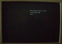
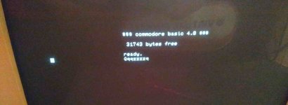
I got this image on my MDA monitor, stable and sharp, connecting directly GND, V-sync, H-Sync and Video from the 8032 to the din-9 monitor connector.

WhatsApp Image 2020-04-18 at 17.51.20.jpg

Three questions:

1) Is there any way to put the image in the right place without to use the flywheel CRT setup?

2) Is there any way to , to setup the brightness? I didn't connect the "intensity" pin... maybe it should be connected somehow...?

3) how can I build a 2k ROM image? I only get 4k ones....
 
>>> 2) Is there any way to , to setup the brightness? I didn't connect the "intensity" pin... maybe it should be connected somehow...?

If I remember correctly, the 'intensity' pin gave you two colour palettes. With intensity = '0' you got dim colours (so white ended up as grey and yellow ended up as brown). With intensity = '1' you got nice, bright colours.

I can't remember what the voltage levels for the intensity pin were though.

You could try just connecting it to the video pin...

>>>3) how can I build a 2k ROM image? I only get 4k ones....

Which 'codebase' are you using? C0 and C1 appear to be the only 2K variants. C2 is the 4K variant. I suspect you may be building the 4K variant with all the 'goodies' possibly?

Dave
 
Last edited:
I also tried the ROM sjg-edit-80-b-ntsc (2017-09-21).bin from the binaries folder, but it still doesn't work (even if I have to say that at least it produces some kind of visible image on a composite output).

This is a 2K binary, but has special code for hard switching between 40 and 80 columns that may need some hardware. Use the sjg-edit-80-b-ntsc (2016) version. Put 2K code into upper address of 2732, i.e., $0800-0FFF. Also there is a code for Invert. I'm not sure what that means. You may have invert the HSYNC or something. I'll ask Steve Gray.

Are you using a composite circuit for video or separate sync signals and video?
 
Some interesting updates....

I used the already built image "sjg-edit-80-n-60 (2018-11-26).bin" (ok, wrong keyboard, it should be the "80-b" image, but it doesn't exist).

I got this image on my MDA monitor, stable and sharp, connecting directly GND, V-sync, H-Sync and Video from the 8032 to the din-9 monitor connector.

View attachment 60308

Wow, so your MDA monitor works with 20 KHz HSYNC? You do not need NTSC frequency? If that is true, just use your normal EDIT ROM to get proper keyboard operation.
 
Wow, so your MDA monitor works with 20 KHz HSYNC? You do not need NTSC frequency? If that is true, just use your normal EDIT ROM to get proper keyboard operation.

well, not really.... nothing is easy....

this is what I got with the edit rom (both 50 or 60hz). Also, I can get the image only if I switch on the monitor before the PET (and the reset button gives the image below).
monitor.jpg

and this is what happens if I move too much the h-hold pot...
h-hold.jpg


...and there's no way to make it working with the NTSC edit rom.
 
>>> 2) Is there any way to , to setup the brightness? I didn't connect the "intensity" pin... maybe it should be connected somehow...?

If I remember correctly, the 'intensity' pin gave you two colour palettes. With intensity = '0' you got dim colours (so white ended up as grey and yellow ended up as brown). With intensity = '1' you got nice, bright colours.

I can't remember what the voltage levels for the intensity pin were though.

You could try just connecting it to the video pin...

I read somewhere you can connect 5V directly. I tried with 5V and a 330 ohm resistor and it increases a bit the brightness , but I ended connecting intensity and video together, this way I don't need to push a spare cable for +5 volts.

>>>3) how can I build a 2k ROM image? I only get 4k ones....

Which 'codebase' are you using? C0 and C1 appear to be the only 2K variants. C2 is the 4K variant. I suspect you may be building the 4K variant with all the 'goodies' possibly?

Dave

Strange, I used codebase c1, and also I respected the instructions about how to build the original edit ROM. No way. I wrote a line to Steve Gray, he suggested to send him the edit.asm

Giovi


EDIT: I missed a note by Steve:
"To generate Edit ROMs that are Byte-exact matches to actual Commodore ROMS set the following options (If an option is not listed assume "0")"

This way it has built a 2k image; I didn't program and eprom yet, I will check it tomorrow.
 
Last edited:
...and there's no way to make it working with the NTSC edit rom.

Ah, that's too bad. I would think the best solution would be to use the NTSC Edit ROM and add a composite video circuit that merges HSYNC, VSYNC and Video data onto an RCA jack. And plug a RCA cable into an old TV or monitor. At most one might have to play with the polarity of the signals. Inversion of the three signals is easy with available jumpers on the PET, or adding an inverter chip on the composite circuit.
 
I was wondering if I can use the cathode tube from my MDA monitor as spare part for my 8032.

I'm not sure how much different could be tubes; I know almost nothing about CRT, so I can't say if there's some risks to simply give a try and swap the broken 8032 green tube with the monochrome white MDA tube, using the 8032 crt board.

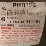
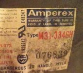
crt mda.jpg MDA

crt 8032.jpg 8032

The size of both tubes is the same.
 
Ah, that's too bad. I would think the best solution would be to use the NTSC Edit ROM and add a composite video circuit that merges HSYNC, VSYNC and Video data onto an RCA jack. And plug a RCA cable into an old TV or monitor. At most one might have to play with the polarity of the signals. Inversion of the three signals is easy with available jumpers on the PET, or adding an inverter chip on the composite circuit.

I tried this one: http://www.6502.org/users/andre/hwinfo/crtc/composite.html#board2 but I can't get an image on a TV with RCA cable, both with NTSC or standard edit rom.

BTW.: I only had 74LS02 so I used it in place of the 74ALS02 in the original project. Could it be the problem?
 
Last edited:
No, an ALS02 is fine. Did you try inverting first the VSYNC, then the HSYNC, then both? It seems like that composite circuit should work at the NTSC frequency. I want you to get it to work since we'll all need to do that when our CRTs go kaput.
 
>>> I was wondering if I can use the cathode tube from my MDA monitor as spare part for my 8032.

I wouldn’t do that unless you get the data sheets for both tubes and compare them...

You can’t put an SN7400 IC in place of a 7402 for example. They are both 14 pin 0.3” wide DIP packages, but the ICs have a completely different function.

You may be lucky of course, but you could also ‘smoke’ the 8032 monitor PCB or damage the MDA tube...

Dave

I found the service manual of my MDA monitor, maybe it could be enough to understand if it's compatible....?
https://ia801306.us.archive.org/29/...A267_MA467_MDA_Mono_Monitor_Service_Mar90.pdf
 
>>>>>>>>>>>> No, an ALS02 is fine.

No, I used LS02 instead of ALS02 because I hadn't ALS here in my toolbox


>>>>>>>>>>>> Did you try inverting first the VSYNC, then the HSYNC, then both? It seems like that composite circuit should work at the NTSC frequency.

looking at the schematics from the project I've built:
did you mean to connect VSYNC directly to IC pin 5, then HSYNC (through C1) directly to C4, then both?


BTW: it seems to me the white, flickering image I got on composite TV has something to do with HSYNC. Maybe I will start there.

>>>>>>>>>>>> I want you to get it to work since we'll all need to do that when our CRTs go kaput.

Ok just explain me what to do, and I will do the job :)

Giovi
 
Back
Top