• Please review our updated Terms and Rules here

PET 8032 Video to MDA Monitor

I haven't found the full technical specifications for the two CRTs - but on first look at the 8032 monitor schematic and the schematic that you provided for your MDA monitor - the CRT pinouts look the same and the heater voltage doesn't look too far out either.

I am not giving you any guarantees, but a transplant may work...

What you have to consider is does the advantages of getting the 8032 monitor to work again outweigh the disadvantages of blowing the 8032 monitor PCB up?

If you are going to try a transplant, I would not have a PET main board connected to the monitor to start with. Just power the monitor up and see if you let the black smoke out of the box to start with! Check that the tube heater doesn't light up like a 100W lightbulb or a nuclear explosion!

Dave
 
>>>>>>>>>>>> No, an ALS02 is fine.

No, I used LS02 instead of ALS02 because I hadn't ALS here in my toolbox


>>>>>>>>>>>> Did you try inverting first the VSYNC, then the HSYNC, then both? It seems like that composite circuit should work at the NTSC frequency.

looking at the schematics from the project I've built:
did you mean to connect VSYNC directly to IC pin 5, then HSYNC (through C1) directly to C4, then both?


BTW: it seems to me the white, flickering image I got on composite TV has something to do with HSYNC. Maybe I will start there.

>>>>>>>>>>>> I want you to get it to work since we'll all need to do that when our CRTs go kaput.

Ok just explain me what to do, and I will do the job :)

Giovi

74LS02 is OK.

We are talking at cross purposes. I am talking about composite video signal where the syncs and video are combined into one signal. Are you talking separate signals into the MDA monitor? I can't tell what schematic you are using. The page you linked has several schematics.
 
I think the composite video circuit shown here has a good chance of working. The signal at J3-pin 4. Although it may need a mod to allow easy inverting of sync signals if necessary.

Composite Video.jpg
 
74LS02 is OK.

We are talking at cross purposes. I am talking about composite video signal where the syncs and video are combined into one signal. Are you talking separate signals into the MDA monitor? I can't tell what schematic you are using. The page you linked has several schematics.


You're right, I should have explained better my ideas. My 8032 tube was broken by the parcel service. So I was trying to find a way to fix it. I tried either composite video out and external MDA monitor, but it didn't work.
So I was wondering if I can extract the tube from my MDA monitor and connect it to the 8032 PCB. I was talking about the chance to do that with the other Dave.


At the same time, I was talking to you about the chance to make the composite video out to work. BTW the board I've built is the "pucoe 1.0c" at this page http://www.6502.org/users/andre/hwinfo/crtc/composite.html#board2 (sorry, I forgot at the same address there was another project too).
 
I haven't found the full technical specifications for the two CRTs - but on first look at the 8032 monitor schematic and the schematic that you provided for your MDA monitor - the CRT pinouts look the same and the heater voltage doesn't look too far out either.

I am not giving you any guarantees, but a transplant may work...

What you have to consider is does the advantages of getting the 8032 monitor to work again outweigh the disadvantages of blowing the 8032 monitor PCB up?

If you are going to try a transplant, I would not have a PET main board connected to the monitor to start with. Just power the monitor up and see if you let the black smoke out of the box to start with! Check that the tube heater doesn't light up like a 100W lightbulb or a nuclear explosion!

Dave
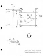
At this moment I have a spare 8032 board and 8032 monitor board, that are almost useless. The MDA monitor is a generic monitor, I can found another on eBay if I will use it for parts.

If it works, I can resuscitate my 8032, that would be fine.


Just a speculation: what could be the worst scenario, in case they aren't compatible?

EDIT: I also need to check the monitor PCB before, I'm not sure it works....
 
Last edited:
>>> Just a speculation: what could be the worst scenario, in case they aren't compatible?

You burn the CRT heater out - the CRT is now recycle material...

You arc internally to the CRT because the voltages are too high for it - potentially damaging both the CRT and the monitor PCB electronics.

You don't damage the CRT - but destroy the monitor PCB electronics.

If you have the PET main board connected - you could destroy all of the logic on that!

Dave

Thank you Dave, now it's clear.... I think -unless I can't get the composite out to work- I will keep my MDA monitor as is, and both 8032 and monitor boards as spare parts for further fix ;)
 
UPDATE: 8032 to VGA?

I found in my tool box the chinese GBS-8220 RGB/CGA/EGA/YUV to VGA converter I bought some time ago for my Sinclair Spectrum+ (and never used yet).

I also found these videos:

https://www.youtube.com/watch?v=eJusmb43jVM
https://www.youtube.com/watch?v=q97NKzQsGwo (english subs)

They successfully connected a Sinclair Spectrum to VGA using the same board. It seems the Spectrum carries a composite sync.

Of course I tried 8032 -> RGB (I connected together RGB pins to 8032 VIDEO pin) -> VGA, but it didn't work, even connecting the H-Sync to the "S" pin (the "S" pin is connected to the "H-Sync pin of the VGA connector).

It also has an RGBHV that carries the h-sync and v-sync as separated signals. I tried, no luck.

I don't know if the problem is the lack of the composite sync, the frequency, or what.

The adapter manual says it has an auto-scan function that detect frequencies in the ranges 14.5 - 16.5k, 23.5 - 25.5k and 30.5 - 32.5k
(here the full pdf manual: https://cdn.shopify.com/s/files/1/0008/4262/9179/files/GBS-8220_VGA-CGA_Manual.pdf)

NOTE: I tried both the NTSC edit ROM and original edit ROM, just to see it it was a matter of frequencies.

Any idea?
 
I lost track of what circuit you are using. Assuming you have a composite video signal and also separate VSYNC and HSYNC signals. Use the NTSC Edit EPROM.

1. Trigger and display HSYNC. Measure the time between pulses. The period should be around 64 uS (15.6 KHz).

2. Use VSYNC to trigger the the scope and also display it on channel 1. Display HSYNC on channel 2. See if you can get a clear photo.

3. Use VSYNC to trigger the scope. Display HSYNC and Composite video if your gadget can show two channels with separate trigger.
If not, trigger on HSYNC and show HSYNC and Composite video. See if you can get good photos.
 
I lost track of what circuit you are using. Assuming you have a composite video signal and also separate VSYNC and HSYNC signals.

ok, of course you're right, let me explain.

I opened two threads:

- one about 8032 to composite video out, using a circuit with a 74LS02:
- this one that started about 8032 to MDA. In this thread I'm not using any DIY circuit.

Since I've seen on youtube a couple of clips about connecting a Sinclair Spectrum to VGA using a chinese converter CGA/EGA to VGA I have, I was wondering if it could process the native 8032 signal in some way and port it to VGA. It seems it can't; there's some kind of a signal (sometimes it appears a solid green screen), but nothing more.

At my post #48 there are links to youtube and the pdf manual of the converter.

Use the NTSC Edit EPROM.

ok

1. Trigger and display HSYNC. Measure the time between pulses. The period should be around 64 uS (15.6 KHz).

2. Use VSYNC to trigger the the scope and also display it on channel 1. Display HSYNC on channel 2. See if you can get a clear photo.

3. Use VSYNC to trigger the scope. Display HSYNC and Composite video if your gadget can show two channels with separate trigger.
If not, trigger on HSYNC and show HSYNC and Composite video. See if you can get good photos.

Since I'm using the native 8032 output, I have no composite video, just hsync, vsync and video out.
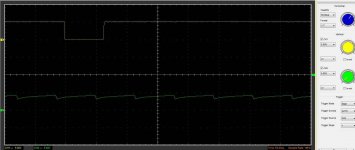
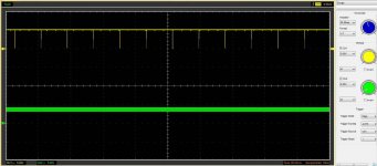
These are the scope results about vertical (CH1, yellow) and horizontal (CH2, green) you asked me, directly from the 8032 board with the NTSC edit ROM. Not sure if it's what you asked for. I have some problems triggering the signal, since I can only choose among fixed time values.

ch1=vertical, ch2=horizontal - 1.jpgch1=vertical, ch2=horizontal - 2.jpg

Using this board to send video output from 8032 to VGA would be fine, since it quite cheap (about 15 USD).
 
These are the scope results about vertical (CH1, yellow) and horizontal (CH2, green) you asked me, directly from the 8032 board with the NTSC edit ROM.

View attachment 60438

I wonder why the HSYNC pulse is not going to ground? Is it a setup problem with the scope? Can you set the sampling rate higher perhaps? You need a better HSYNC if the picture is real.
 
I wonder why the HSYNC pulse is not going to ground? Is it a setup problem with the scope? Can you set the sampling rate higher perhaps? You need a better HSYNC if the picture is real.

Sorry, my fault. Since I don't know what to expect, I didn't see the mistake.

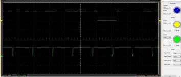
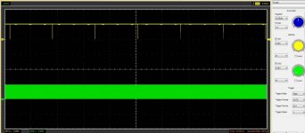
Now it should be ok (at least, this what is coming from the PET connector, no devices connected).

ch1=vertical, ch2=horizontal - 1.jpgch1=vertical, ch2=horizontal - 2.jpg

I tried again to connect it to the board, nothing more than a green screen for few seconds.

(BTW the above images were taken with the NTSC ROM; however I tried the converter board with both NTSC and original edit ROMs).
 
>The adapter manual says it has an auto-scan function that detect frequencies in the ranges 14.5 - 16.5k, 23.5 - 25.5k and 30.5 - 32.5k<

The normal 8032 EDIT ROM produces a 20 KHZ HSYNC so the 'adapter' will not work as it skips that range. You had your best chance with the NTSC frequency of 15.7 KHz which you proved the Steve Gray ROM is producing.

However, in that frequency the adapter can only use a CGA video format. I don't know about the CGA format. How are you converting the PET monochrome to the CGA color? Is it even possible? In the old days, when I connected a B&W monitor/TV to the CGA PC card, I always used the composite video RCA jack.

You should try and ask Hugo Holden for his recommendation for a PET compatible composite video circuit that assumes the Steve ROM with the NTSC timing. Then hook it up to a video terminal, security monitor or old analog TV (as long as they have a composite video input).
 
How are you converting the PET monochrome to the CGA color? Is it even possible?

Some adapters have the capabilities to take an MDA input simply connecting the video output to the three R G B pins. Since the 8032 generates some output on my MDA monitor, I was intrigued if the board was smart enough to manage the output.

https://www.youtube.com/watch?v=I2z0ITaccyA

Worth to mention the guy in this video tells explicitly cheap boards like mine will not work... but I already had it at home, and the one he's using is quite expensive... to much for a simple test without any guarantee.


You should try and ask Hugo Holden for his recommendation for a PET compatible composite video circuit that assumes the Steve ROM with the NTSC timing. Then hook it up to a video terminal, security monitor or old analog TV (as long as they have a composite video input).

Yup, it seems to be the only chance lasted. However I'm not very confident about composite video, even if it will work, the quality will be really bad, expecially for an 80 columns video. Would be ok for a 40 cols like 3032 or 4032... or C=64. But, also, would be better than nothing, at least for fixing purpose.

cheers,
Giovi
 
However I'm not very confident about composite video, even if it will work, the quality will be really bad, expecially for an 80 columns video. Would be ok for a 40 cols like 3032 or 4032... or C=64. But, also, would be better than nothing, at least for fixing purpose.

cheers,
Giovi

Actually it is not the composite video signal itself that has the problem. It is the video bandwidth capability and focused spot size and focus of the monitor. Unless say there was loss of HF response if the circuit could not properly drive 75R coax. But most commercial small CRT monitors (security monitors etc) are up to good resolution of they are in new order. Industrial style open frame monochrome VDU's are often very good as many of their applications included graphics.

Mostly for TV images they only had to support a 4 to 5MHz bandwidth in the video amplifier and maybe twice that in some computer monitors.

Pretty well all the small monochrome monitors I have tried with a direct video feed are fine for computer graphics with a composite signal (they only are poor if you feed a typical mono TV set with an RF modulator which degrades the resolution significantly). Color monitors are not as good unless special types of CRT's with very fine pitch phosphors.

It is true that some monochrome video monitors are better than others. A classic good one for example is the small amber monitor in the IBM5155. These are driven by a composite signal, have an 8MHz video bandwidth and a very high intensity small focused spot size which maintains its focus over a wide range of beam currents and as a result the graphics are as sharp as a tack, much better than on a color monitor. Its not the actual composite signal that is an issue.

Have a look at page 5 and 6 of this article, how the shadow mask and beam scatter degrades the apparent resolution of a color CRT compared to a monochrome one:

http://worldphaco.com/uploads/INCREASING_THE_UTILITY_OF_THE_IBM_5153_COLOR_MONITOR_TO_AUTO.pdf
 
Last edited:
SOLVED - I'm leaving here my comments about how to plug an 8032 to an MDA monitor.

(See also this thread, since many informations about it are there: http://www.vcfed.org/forum/showthread.php?45170-Composite-picture-from-a-CRTC-PET )

I want first to say a big thank-you to all the friends that helped me, expecially Hugo Holden, the two Dave (Dave_m and Daver2), and Mike (MikeS) that pulled the rabbit out of a hat, giving me the clue that simplify a lot the whole process. Hope I didn't forget anybody!


My MDA monitor is a Samsung MA2671; it didn't complain about the slightly different frequency between MDA specs and 8032 board. Probably (almost) any MDA monitor will work fine...


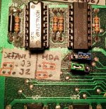
I only needed to change the J2 and J3 jumpers.

J2 (UC2 7486 pin 5) must to be connected to PULLUP
J3 (UC2 7486 pin 2) must to be connected to GND

The Edit ROM is the 901474-04, basic 4, business keyboard, 50Hz. The Steve Gray's NTSC modified doesn't work for this purpose.

This is the video cable pinout:

8032 video | MDA
connector J7 | Plug
---------+-------------+------
video out| 1 | 7
V-Sync | 3 | 9
H-Sync | 5 | 8
Intensity| 1 (*) | 6
GND | 2,4,7 | 1+2

(*) 8032 hasn't an intensity line. I connected the MDA intensity pin to video out and it worked fine, resulting in a brighter image.

-----------------------------------------------------------

Since my CRT was broken, I transplanted the MDA monitor into the 8032 case. It required about one day, because the Samsung board has a very different shape and I had to remove and re-wire some parts (an electrolytic capacitor, the TIP42 transistor and its heat-sink, the sub bright potentiometer, a power resistor, and of course the AC transformer).

The monitor had two potentiometers for brightness (I glued it into the properly hole at the back of the 8032 case) and contrast (I simply left it inside the case, since I don't really need to change the contrast).

Since I had to rotate the Samsung board, I had to extend some wires of the small sub-board with the socket that plugs in the tube connector, and the 4 wires of the deflection coils (I put a connector, since they were soldered directly to the pcb)

Then I cut the video cable and I put the video and AC wires into a connector that fit the original 8032 CRT connector.

Since the Samsung tube has a little different shape, the front, black bezel doesn't fit very well; I had to make some changes with my Dremel and the result isn't amazing because there's some space between the tube and the bezel... but I don't care about it, really...

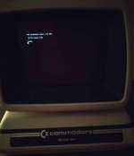
WhatsApp Image 2020-05-04 at 18.01.21(1).jpg


Giovi,
Nice that you fitted everything in the PET chassis. Congratulations! Please keep schematics and all information on the modification inside the PET chassis as documentation for future users of this PET as your PET is now quite unique.
-Dave
 
Giovi,
Nice that you fitted everything in the PET chassis. Congratulations! Please keep schematics and all information on the modification inside the PET chassis as documentation for future users of this PET as your PET is now quite unique.
-Dave

Dave, the only modification I did on the 8032 board was to set the two jumpers (J2 and J3) and connect the PET to the MDA using the following pinout (I'm copying it here because my previous message was messed up).
Inside the 8032 monitor case I only moved some components in another place, some kind of logistic setup.

8032 video.......| MDA
connector J7.....| Plug
---------+-------+------
video out|.1.....| 7
V-Sync...|.3.....| 9
H-Sync...|.5.....| 8
Intensity| 1 (*) | 6
GND......| 2,4,7 | 1+2

(*) 8032 hasn't an intensity line. I connected the MDA intensity pin to video out and it worked fine, resulting in a brighter image.


WhatsApp Image 2020-05-04 at 20.49.50.jpg
 
Last edited:
Back
Top