Upcoming Events:
| VCF West | Aug 01 - 02 2025, | CHM, Mountain View, CA |
| VCF Midwest | Sep 13 - 14 2025, | Schaumburg, IL |
| VCF Montreal | Jan 24 - 25, 2026, | RMC Saint Jean, Montreal, Canada |
| VCF SoCal | Feb 14 - 15, 2026, | Hotel Fera, Orange CA |
| VCF Southwest | May 29 - 31, 2026, | Westin Dallas Fort Worth Airport |
| VCF Southeast | June, 2026 | Atlanta, GA |
-
Please review our updated Terms and Rules here
You are using an out of date browser. It may not display this or other websites correctly.
You should upgrade or use an alternative browser.
You should upgrade or use an alternative browser.
PET cemetery - 4016 repair
- Thread starter plagued
- Start date
daver2
10k Member
Ok, so that is my 'puzzler' for Christmas day...
The data for each character (ESDn) goes through the 8-bit latch and into the character generator.
I have noticed an interesting aberration in your posts though...
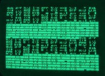
In post #98 the sequence of non inverted characters and inverted characters is correct - albeit with each pair of characters swapped over.
It is still OK in post #99 with the SA0 to ESD0 link removed.
In post #101 though we have a change to the non-inverted / inverted character sequence.
If all post #101 has done is to remove the SA0 to ESD0 link and pull ESD0 to ground - that has also affected ESD7...
Dave
ahh, my bad ... either I had a loose connection or I was messing with SA7 at the time. it does only affects the order, the inversion is the same SA7 is unaffected.
I wouldn't want to ruin your christmas gift of commodore diagnostics with misleading information
I wouldn't want to ruin your christmas gift of commodore diagnostics with misleading information
I haven't had much time to look much further into the issue as we've had family over, and then a visit from the Flu... Joy!, but I've taken some time to do a bit of house keeping.
I've gone over the board with a microscope to check my work and look for any other signs of issues, everything looks good.
I did have some slightly odd glitching which seemed to change after things warmed up. This seemed to be related to the last few original sockets on the board to the CPU, and ROMS. I'd already tried cleaning and deoxit, so I have now replaced these and have a nice "clean" broken and glitched screen. So nothing related to our previous issues, but needed doing.
I also pulled the buffers at UD14 and UD13 (AB and BA lines) to test them as I traced a few of the failures on the basis of a power spike and UD14 was connected to 4 other failed chips. They tested Fine
I had already pulled and checked the buffers at UB4 and UB5 (ESD and BD lines) when I was initially diagnosing the issue that turned out to be failed SRAM.
This is what I know so far -
All ROMS read OK with a valid CRC. I had to replace two as they had failed, but I am currently only running the kernal, PETTESTER and Character ROMS, the other sockets are empty.
I can remove the serial and parallel controllers (UB12, 15, 16) and just run the CPU and CRTC and have the same issue.
The multiplexers on UD8, 9 ,10 - I replaced 10 as it was faulty, I also pulled UD8 as it's on SA0 and was corroded. It tested fine and has been cleaned and socketed. UD9 seems OK when looking at the logic so I have left alone.
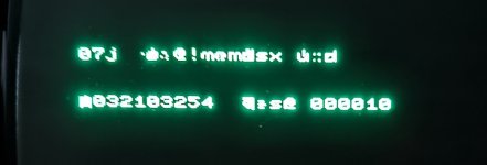
The PETTEST memory test seems to run and pass. the screen is fairly garbled but you can see it running through and it never displays a fail message:
I cannot see, with a logic analyser, any issues with UD3, and a quick piggyback of a spare makes no difference. But I've not pulled it.
That's where I'm up to.
I've gone over the board with a microscope to check my work and look for any other signs of issues, everything looks good.
I did have some slightly odd glitching which seemed to change after things warmed up. This seemed to be related to the last few original sockets on the board to the CPU, and ROMS. I'd already tried cleaning and deoxit, so I have now replaced these and have a nice "clean" broken and glitched screen. So nothing related to our previous issues, but needed doing.
I also pulled the buffers at UD14 and UD13 (AB and BA lines) to test them as I traced a few of the failures on the basis of a power spike and UD14 was connected to 4 other failed chips. They tested Fine
I had already pulled and checked the buffers at UB4 and UB5 (ESD and BD lines) when I was initially diagnosing the issue that turned out to be failed SRAM.
This is what I know so far -
All ROMS read OK with a valid CRC. I had to replace two as they had failed, but I am currently only running the kernal, PETTESTER and Character ROMS, the other sockets are empty.
I can remove the serial and parallel controllers (UB12, 15, 16) and just run the CPU and CRTC and have the same issue.
The multiplexers on UD8, 9 ,10 - I replaced 10 as it was faulty, I also pulled UD8 as it's on SA0 and was corroded. It tested fine and has been cleaned and socketed. UD9 seems OK when looking at the logic so I have left alone.
The PETTEST memory test seems to run and pass. the screen is fairly garbled but you can see it running through and it never displays a fail message:

I cannot see, with a logic analyser, any issues with UD3, and a quick piggyback of a spare makes no difference. But I've not pulled it.
That's where I'm up to.
daver2
10k Member
I will read your post a bit later.
Well, PETTESTER seems to be running OK and it seems to be testing the DRAM as well.
We just have a pesky video issue somewhere...
Dave
Well, PETTESTER seems to be running OK and it seems to be testing the DRAM as well.
We just have a pesky video issue somewhere...
Dave
I've had another look over it this weekend.
I did pull the two ub1 ub2 flipflops, despite all my tests showing thy were fine. And they were fine so I had to stop myself pulling chips I knew were ok. So I've gone back over everything and the only thing it could be was the character ROM. I'd used a known good SGS EPROM and it read back and verified fine and also read correctly in the retro chip tester. But as I was out of ideas I burned a new one onto a different brand and this partially fixed the issue. The characters are in the correct order but the screen was full of interference, which went away if I reinstalled the SGS chip. I then made a small adapter and burned 32 copies onto a winbond 27C512 to be 100% I didn't have a response timing issue. This gave the same result but with a lot less interference
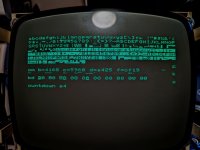
You can see here that everything is shifted over 1 character and the first character is missing.
The screen of "g" is also now ok with no random slash.
I can get rid of the interference by placing my fingers over the character rom (resistance not physical pressure making the difference. Pressing with a plastic screwdriver makes no difference) I'm not too fussed about the interference for now, but I'm happy that something has actually made a difference even if it's still not right.
I did pull the two ub1 ub2 flipflops, despite all my tests showing thy were fine. And they were fine so I had to stop myself pulling chips I knew were ok. So I've gone back over everything and the only thing it could be was the character ROM. I'd used a known good SGS EPROM and it read back and verified fine and also read correctly in the retro chip tester. But as I was out of ideas I burned a new one onto a different brand and this partially fixed the issue. The characters are in the correct order but the screen was full of interference, which went away if I reinstalled the SGS chip. I then made a small adapter and burned 32 copies onto a winbond 27C512 to be 100% I didn't have a response timing issue. This gave the same result but with a lot less interference

You can see here that everything is shifted over 1 character and the first character is missing.
The screen of "g" is also now ok with no random slash.
I can get rid of the interference by placing my fingers over the character rom (resistance not physical pressure making the difference. Pressing with a plastic screwdriver makes no difference) I'm not too fussed about the interference for now, but I'm happy that something has actually made a difference even if it's still not right.
daver2
10k Member
The character shift and the interference is most likely caused by the access time of the video RAM and/or EPROM used. One cause could be one device and another cause the other.
Dave
Dave
Well it's been a long time coming ...but
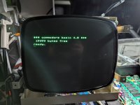
This was, in many ways, a bit frustrating. I'd gone over the board and was sure all the logic, buffers, voltages, timing etc were spot on. I tried 4 different makes of 2114 vram chips and 3 different character rom replacements and ended up having to walk away a few times as I found myself pulling chips I knew were fine.
The issue was that my board seems especially fussy about the character rom.....
SGS M2716-IFI resulted in the back to front characters
ST M2716A-IFI resulted in the correct character order but the first character missing and a lot of noise on the screen
Winbond W27C512-45z behaved in the same way as the above ST chip but with a lot less noise
And then the winner was .....
ST M2716A-IFI FAST - Which seems to work perfectly, but was of course the last one I tried, and not until I'd exhausted all other possible causes.
The last issue to getting it booting was the UD7 ROM was faulty, which I'm kicking myself as I'd mistakenly thought UD6 was dead (I'd identified and two dead ROMS UD6... or so I though and UD10) , only to later retest UD6 with a bit of confusion as to why it was now working ... and the reason why it sprang to life was likely that it was UD7 that was faulty all along and I'd mixed them up when testing.
so 13 dead IC's in the end, which is a bit higher than I was expecting for a "it was working when I last used it" machine
I don't actually have any way to load anything on it at the moment, so I'll leave the more thorough testing until later, but it passes the PPETTESTER tests.
Time to get it back together......
daver2
10k Member
Well done!
A bit of persistance pays off in the end...
Before you put it back together though, there is an IEEE488 BASIC test program. I would locate a copy and type it in to see if your IEEE488 buffers are OK...
It is in a book, and I have made numerous references to it in threads here.
Dave
A bit of persistance pays off in the end...
Before you put it back together though, there is an IEEE488 BASIC test program. I would locate a copy and type it in to see if your IEEE488 buffers are OK...
It is in a book, and I have made numerous references to it in threads here.
Dave
Hugo Holden
Veteran Member
Character ROMs for ultimate video signal production have to be very fast parts.
Ohhh...... can't I just pretend it's all working and be happy!Before you put it back together though, there is an IEEE488 BASIC test program. I would locate a copy and type it in to see if your IEEE488 buffers are OK...
Ok ... here we go again, to run the program I'll need a working keyboard ... which while I thought I may just have a few dirty key contacts (even after giving it a good clean) it became apparent that I had a sequence of keys not working across the top row with the things I needed to type like "(" the key mappings showed I had an issue with "0" or pin 1 in the middle of the connector. There wasn't anything visible other than a mark on the trace which turned out to not be the issue, but it was clear that I had no continuity between the jumper bridge over to that point and giving it a very gently poke caused it to disintegrate.
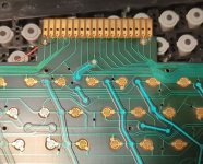
So with a bodge wire in place I could start that laborious job of typing the code in, which is luckily in small sections so I could lazily just type in the first test and watch it .... fail
THE BAD GPIB DATA BITS ARE: BIT 2
From what I can gather from this test we're poking the 6520 to set data on the ieee-488 bus and then reading it back.
I can easily swap over the two 6520's to see if one is faulty as my keyboard should stop working ....again.
If not I'm assuming I likely have an issue with a trace over to one of the bus transceivers, or the transceiver itself?
Is BIT2 referring to the DI-2 and DO-2 lines on UB17
I'm at work at the minute (very busily working I'll have you know! and NOT reading commodore schematics) otherwise I'd be swapping/poking IC's rather than typing this.
daver2
10k Member
Too good to be true!
A message stating BIT 2 is DI-3, DO-3 and DIO-3 on the schematic.
The program counts from data bit 0 but the schematic starts at DI-1 and DO-1.
You should now be able to check to see if DO-3 changes state when you perform the POKEs, and follow the changes through to the bus on DIO-3 and further on to DI-3.
The lower four (4) data bits are all on the same buffer, so if it is not the PIA it must be the buffer.
Dave
daver2
10k Member
How do you know it is the buffer holding DO-3 low?
Why not the PIA faulty?
Dave
Why not the PIA faulty?
Dave
SiriusHardware
Veteran Member
Certainly you can eliminate the 6520s from the equation by swapping them, which - providing they are in sockets - is probably faster than logically tracing the signals although the latter is always the more satisfying way to find faults. However I have to say that in all cases of faulty PET IEEE 488 ports that I have seen, the fault has been down to failure of one or more elements in the associated 3446 buffer.
Once you've eliminated the 6520s, socket the 3446 buffers, or at least the two which handle data bits 0 to 7, and swap them over. You should find that the reported error moves from bit 2 to bit 6. By doing so, you can prove that there is (...or is not) a need to obtain a replacement buffer IC before spending money on one.
Once you've eliminated the 6520s, socket the 3446 buffers, or at least the two which handle data bits 0 to 7, and swap them over. You should find that the reported error moves from bit 2 to bit 6. By doing so, you can prove that there is (...or is not) a need to obtain a replacement buffer IC before spending money on one.
Yes, the first thing I tried was swapping the 6520's which made no difference, then checking the DO lines when idle and they were all above 2.5v (although a few were borderline, so possibly pending failure) other than DO-3 which was low. Removing the 6520 and reinserting it with pinstrip with pin 12 removed (don't dare bend the legs on the 6520 out of the way due to corrosion) and it's high, so being pulled down by the 3446. No trace damage or bridged pins.
I'll pull all three 3446 out and socket them as it's an easy board to work on and socketing any ICs that are prone to failure should make future repairs easier. If I have one bad and one looking sick even if the other is fine it's probably not long behind. And as you said, makes testing faults easier if I can swap them about.
Cheers
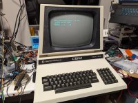
I got my more-expensive-than-i-would-have-liked MC3446 chips today and popped them in. Two were faulty, so I swapped them over and ran through the tests.
GPIB was now good but NDAC was bad..... so I'd made it to test 2 out of 6 before hitting my second failure.... The signals to the MC3446 looked ok so I grabbed a spare 6522, on swapping this out I noticed two things -
The beeper now worked on boot up, an issue I had noticed but had not looked into, and my fonts were now in uppercase not lowercase. The 6522 was bad!
I ran through the next tests full expecting it to now fail on test 3 ... but it's all now good apparently.
So it's back together and I'm going to say it's fixed!!! and if Dave comes back and says it's NOT fixed until I run a load more tests, I'm just going to pretend I didn't hear him and enjoy a large whisky in celebration
The maybe-final tally is:
3 x ROM chips
2 x MC3446
2 x 2114 SRAM
4 x DRAM
1 x 74154
1 x 555
1 x 74LS10
1 x 74LS157
1 x 6502
1 x 6522
Thanks for all the help so far!!! I have a 8050 floppy on the shelf that I'll have a look at some time soon!
Hugo Holden
Veteran Member
Well done. The only thing that surprises me on that list is the 74154.View attachment 1294980
I got my more-expensive-than-i-would-have-liked MC3446 chips today and popped them in. Two were faulty, so I swapped them over and ran through the tests.
GPIB was now good but NDAC was bad..... so I'd made it to test 2 out of 6 before hitting my second failure.... The signals to the MC3446 looked ok so I grabbed a spare 6522, on swapping this out I noticed two things -
The beeper now worked on boot up, an issue I had noticed but had not looked into, and my fonts were now in uppercase not lowercase. The 6522 was bad!
I ran through the next tests full expecting it to now fail on test 3 ... but it's all now good apparently.
So it's back together and I'm going to say it's fixed!!! and if Dave comes back and says it's NOT fixed until I run a load more tests, I'm just going to pretend I didn't hear him and enjoy a large whisky in celebration
The maybe-final tally is:
3 x ROM chips
2 x MC3446
2 x 2114 SRAM
4 x DRAM
1 x 74154
1 x 555
1 x 74LS10
1 x 74LS157
1 x 6502
1 x 6522
Thanks for all the help so far!!! I have a 8050 floppy on the shelf that I'll have a look at some time soon!

