• Please review our updated Terms and Rules here

PETunia's Repair Log

I measured nRESET versus phi0...

phi0_vs_nRESET.jpg

and zoomed in...

phi0_vs_nRESET_zoom.jpg

So clock happily running before nRESET goes high

and a better view...

phi0_vs_nRESET_better_capture.jpg

Shows 555 triggers around 1s after power comes online.... clock working within 200ms.
 
Last edited:
That look fine then...

Did you remove the replacement VIA to see if you returned to a ‘working’ machine once again?
Dave
 
Did you remove the replacement VIA to see if you returned to a ‘working’ machine once again?
Yeap... it doesn't boot to a cursor but a soft reset will reset it to the cursor state and workable with the VIA removed. I also tried the original VIA and it doesn't boot with that either (I had assumed it was a defective VIA... maybe not).
 
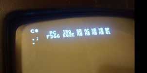
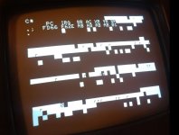
I checked out some signals at the VIA socket and CS1, nCS2, RA0, RA1, RA2 & RA3 look OK. Checked some other signals and again cannot spot anything... Anyway I put the board back into the chassis and removed all PIAs and the VIA, I then replaced the PIA#1 with a replacement and to my surprise it would not boot to anything except blank (but a soft reset will get it to a flashing prompt) very much like behaviour seen before... anyway... My ROM board has a number of images so I switched to 'Basic 2'... and the behaviour is a bit different... I get a screen with some hex numbers and occasionally get garbled characters and the hex... with a soft reset it goes on to a good flashing cursor.

Basic2.JPG

and

Basic2_BadStart.JPG

or

Basic2_BadStart2.JPG

or

Basic2_BadStart3.JPG

The FD66 variant seems repeatable 6 times out of 10


And another observation.... when the ROM SET which includes the PETTESTER is selected the PET starts from cold... every time...
 
Last edited:
You might try some freeze spray on things. It may be that it has a marginal connection and once the parts warm up a little, it will rest.
Dwight
 
The ‘hex numbers’ are TIM (the machine code monitor), however, the random characters on the screen are not correct.

The ROMs check the DIAG pin on power-up and (if pulled low) enters TIM rather than BASIC.

Removing the PIA associated with the DIAG signal could cause the CPU to misread the DIAG pin and enter TIM as a result. However, in this case, TIM should be operational (the manual is available on the internet).

The interesting thing is the soft reset...

Do what Dwight says first (hair dryer to heat and buy a can of freezer spray to cool).

The other thing would be to try and ‘see’ what the CPU is doing on a cold power-up when compared to a warm power-up.

Check the state of the /IRQ and SYNC pins of the CPU to start with and then check the state of the 16 outputs from the 154 4 to 16 decoder to see what blocks of 4K the executing program is touching. This would be akin to fingerprinting the machine. Then perform the same checks after warm resetting and look for differences.

Dave
 
Do what Dwight says first (hair dryer to heat and buy a can of freezer spray to cool).
I did try freeze spray before, particularly on the 75154 and 6x 74LS244s but could not see any change in signals or behaviour. I don't have the chassis and monitor accessible when it is on the bench so I am working blind there though so cannot see the whole boot (or non-boot) sequence.
I will try and add the VIA and see what happens with BASIC2.
When it boots to the TIM it is hung (no cursor no keyboard etc) so at that point it is very confused.
Does the flashing cursor behaviour rely on interrupts?
 
The DIAG jumper is on the same PIA as the keyboard. So, if that PIA goes faulty (or gets confused) it could enter TIM and have the keyboard not working simultaneously.

Yes, the flashing cursor uses interrupts as the timing. So, no flashing cursor could indicate an interrupt problem. This is certainly the first signal I would check with my oscilloscope.

Dave
 
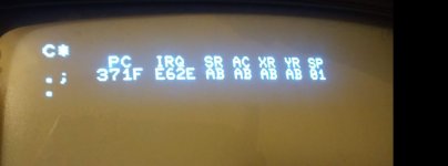
In the screen images above one of them shows a PC of 371F which clearly doesn't sound feasible.... and the screen images show corruptions... which are interestingly striped... suggests to me the data bus is contended during the screen clear so an attempt to write a $20 actually ends up writing something else.

I'm confident in my PIA since it passes the PETTEST nicely by showing the keyboard scan.... so I think that suggests data bus contention early on... but that could be many many things...
 
I am not making any material progress but... I removed H8 and H9 the buffers to the onboard RAM section... no change.

And I replaced CR3 the rectifier on the DC side... no change.

And I socketed and replaced the 74LS04 at E5... (because pin 9 and 8 are the inverter for the SEL8 signal)... no change

And I socketed and replaced the 74LS00 at C2... (because pin 12,13 in and 11 out)... are used for the B3/B4 drivers... no change

And I measured with an LCR meter all the ceramics and the few electrolyics... they seem OK.

So there are a few more things that I know are probably not the problem! :confused:
 
I noticed that when started from cold the nIRQ line appears to be flat lined but on soft restart I see periodic (blanking period) interrupts. Tapping the area of the board around C/D/E 2/3 sometimes brings it back but this could be just by glitching the CPU add-on board socket.

I'm doing this blind as I don't have the PET monitor near my desk... I do have a small Sony PVM I bought at auction many years ago (may not work as I never turned it on!)... could I use that somehow to see what is going on?

I have ordered a 74LS157 which I plan to try at D2... since that is directly responsible for control of the buffers at B3/B4... still clutching at straws really.
 
But flatlined high or flatlined low?

Where is the flatlining in relation to the RESET signal?

At power-up, (after the +5V has been applied), the /IRQ line should be HIGH.

The /RESET signal should be LOW when the RESET is being applied.

After the /RESET pin has gone 'HIGH', the PET should initialise the I/O devices (part of the EDIT ROM) and you should start to see little /IRQ pulses going LOW.

If, just before the /RESET signal goes HIGH, the /IRQ signal is LOW - we have problems...

Dave
 
Last edited:
But flatlined high or flatlined low?
Where is the flatlining in relation to the RESET signal?
From memory, it is flatline low and independent of nRESET.
I'm pretty confident that I have a problem with the 74LS157 at D2 and that could explain a few things... in particular I don't think pin 19 of B3 and B4 are driven hard enough. I don't have a spare 74LS157 so will have to wait until Mouser process my order.
One behaviour I have seen is with the VIA installed and booting into Basic4 it basically starts (on soft reset) in slo-mo... the banner paints really really slowly... that could be CPU starvation due to constant nIRQ being low? Anyway I think I still have multiple issues but hopefully swapping D2 will do something.
 
Flatlining /IRQ LOW is BAD...

It should never flatline LOW if the PIA and VIA devices are removed. Remove them and prove this. You should get the BASIC logo on start-up from cold even time - you will just not get a flashing cursor. But this should tell us something major.
This may also account why your machine works with my PETTESTER - my code doesn't use interrupts and doesn't enable the maskable interrupt either.

Yes, slo-mo is also another good indication of /IRQ problems.

Swapping D2 could fix your display issues (crossed fingers). However, I thought we agreed it was D4 back in a previous post?

Dave
 
Last edited:
It should never flatline LOW if the PIA and VIA devices are removed. Remove them and prove this.
With no PIAs and no VIA it just pulls up High. This is with PIA#1 and VIA#1 fitted... I'm trying to work out why adding a VIA stops anything working... which it does for Basic 1 and 2 and makes Basic 4 go on a slow version.
Re: D4... I will have to look back; I suspect D2.
 
It's been a while but I had to wait for a 74LS157 and some DIP16 sockets...

Firstly, an admission :sigh: I looked very very hard at the reset circuit and established that everything was OK with the 555... 1M ohm in the right places, 1uF in the right place etc and followed the 74LS04 inverter (D9) and then had a eureka moment... My add-on memory board/NOPper reset circuit was totally bogus... it was pulling nRESET high on startup. Sorry for the confusion... fixed it and it does reset correctly now so that is huge progress. I still think I fixed an earlier reset issue since it had the same symptoms without the add-on board... anyway... reset is now deterministic so that is a huge step forward.

As previously mentioned I noticed that pin 19 of the buffers at B3 and B4 was around 3V6 so I replaced the multiplexer 74LS157 at D2. Pin 2 of D2 drives pin 19 of B3 and B4. The removed 74LS157 tests OK with my cheapo ebay Chinese chip-tester but when I replaced it with a new one it now drives at >4V2 so an improvement.

My theory is the B3 and/or B4 are driving in both directions simultaneously so I removed and socketed these... and again my tester says they are OK but I replaced them anyway.

The current state is I have all ROM and RAM replaced, buffers at G5 and G6 are removed (now empty sockets), PIA#2 and VIA#1 sockets are empty but things are looking pretty good.

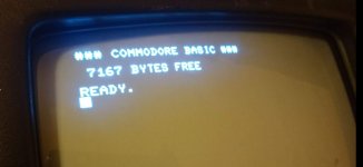
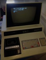
Boots every time to... (with flashing cursor and keyboard working)...

She lives!

Capture.JPG
 
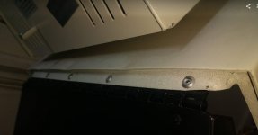
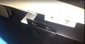
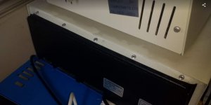
Away from the electronics I have a physical issue with the case... at some point in its previous life the bracket at the back has been bent so the screw holes and bracket do not line up...

Capture.JPG

Capture2.JPG

Capture3.JPG

It's like it was bent back on itself once and the top case bent rather than the hinge.

Should I drill the rivets and try and bend it? I don't think I could rivet it back since my hand rivet gun would not reach... nuts and bolts?
 
I'm not a big fan of those programmers, turned logic tester. In circuit function is always the best indication. I saw something funny in your reset schematic but didn't say anything because I couldn't figure how you were connecting it.
Anyway, it is looking good. Another pet is alive.
As for the bent metal, I suspect it was dropped. Does the hinge work freely? If so, it may recover by applying force in the right places. If not you'll have to drill the rivets and work on it when apart.
Dwight
 
Last edited:
Back
Top