• Please review our updated Terms and Rules here

Project to create an ATX 80286 mainboard based on the IBM 5170

Good news, I have run a Wolf3D test game demo of more than 4 hours and another one of 5:30 hours. So that's reasonably stable.

In the past I have tried several times to run the DMA controllers at 4,77Mhz instead of 4Mhz as was done in the 5170.

4,77Mhz is divided down from the OSC clock signal on the ISA slot of 14,318 Mhz, which also means that the DMA controller clock would not b e in sync with the 286_CLK and main CPU clock. It has been my theory all along that just like with the XT, it's not necessary to derive and sync the DMA clock from the main CPU clock for operating the DMA controllers.

In the past I was still having trouble with stability so I could not run a lengthy stable test with the DMA controllers at faster clock speed. After some variation in the results I would usually return the DMA controllers to 4Mhz at the time.

Since I have now solved the remaining problems by using faster EEPROM chips instead of EPROMs, this time I clocked the DMA controllers from the OSC clock divided by 3 and asynchronous to the main CPU clock once again for another test at 4,77 Mhz. As expected, the handshaking between the CPU and the DMA controllers to release the bus and return it back to the CPU enables DMA to work properly using this configuration, even at 16Mhz CPU clock. Today I was finally able to indicate this in a stable test by running a Wolf3D game demo for more than 7 hours, and the system is still running now without any issues.

Using a faster clock on the DMA controllers has the added benefit of a slightly faster DMA performance so it's great that this is possible. Faster DMA operation also means more CPU execution time on the bus, so this provides an additional performance increase in terms of extra CPU cycles.

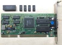
Next I will test the memory card to run completely on HCT transceivers. I believe this could help with higher CPU clock speed tests later on because the signals on the RAMs will have much better amplitudes compared to LS or ALS logic.

If I find some faster Harris CPUs I will write about the results here as soon as I am able to test these. For these tests I will look at more detail at the crystal inputs of the 82284 in order to determine if I can provide the 40Mhz and 50Mhz from an external oscillator directly into these inputs. Otherwise I would need to find some even faster crystals. I am not saying that this would be impossible but I would prefer to use the construction of the external oscillator at 40Mhz or 50Mhz 286_CLK. This would be well above the 24Mhz specification of the 82284 I am using, but that's not to say that it would not be able to run. Right now the 82284 is already running at 32Mhz without any problems. The only thing which is nearing now is that the PCB load capacitance would become too high. Possibly I would need something else on the crystal if using a crystal of 40 or 50 Mhz, if I can find one, to keep it in oscillation on the 82284 inputs, like a circuit using a coil or something like that. Anyway, I would prefer an oscillator chip on the crystal inputs instead. As soon as I am able to determine if this is possible I will write about it. I tried before with the EFI input at 33Mhz, however at that time I was not even able to POST the system in my tests. So that's why I want to attempt using an oscillator on one of the crystal inputs to see how that runs.

Kind regards,

Rodney
 
I have done more testing at 16Mhz with the DMA controllers at 4,77Mhz, and the transceivers on the memory card all replaced by 74HCT245 chips.

This configuration so far works the best. It's my usual process when debugging a new system to first get the system running and then start to replace as much as possible of any TTL chips with HCT or HC logic. So it's great to find out that with the AT, this is also the best configuration.
I managed to do demo test runs of 12 hours without any freeze or glitch at all. So I can conclude that this provides even more stable operation than before. I may have reached fully stable condition but maybe I am a little premature to think this. Even running for 24 hours, the system never got into an unstable mode. I will do more tests of continuous operation for longer duration than that. For now, I will keep the system on the 4MB of 50ns SRAMs which I have, and only later I will add more SRAMs again for testing because I only have 70ns SRAMs available to add.

I found and ordered a Harris 286 CPU that is supposed to be a 20Mhz chip. Of course, I can't know completely for sure, this chip is coming from New Zealand and I believe the supplier is a very reliable person. This Harris CPU will take around 4 weeks possibly to arrive here.

In the mean time, I decided to have some first tries at 20Mhz operation with the current 16Mhz Harris 286 CPU.
First of all, I determined the correct method to directly "inject" an oscillator chip clock signal into the 82284 chip, so not using the EFI input but the normal crystal input pins. This can be done by connecting the oscillator clock with pin 8 of the 82284, which is input X2. Additionally I discovered that doing this possibly may work a little better and more stable when using a series resistor of 100 ohms or perhaps more between the oscillator chip and the 82284. I wired an oscillator of 33Mhz to the X2 pin first using a 100 ohms resistor and a bypass capacitor soldered directly to the oscillator pins. This enabled the clock input on the 82284 to be driven by the oscillator and resulted in a the system POSTing and showing a display, and the MR BIOS correctly showing that the clock was 16.5Mhz, so I have found a successful method to experiment with and proceeded with a 40Mhz oscillator.

It's all about the access times which is the real issue when speeding up the CPU.
Particularly the VGA adapter card was the first and main thing I noticed to pose some difficulties.
There are several components involved when trying to access the VGA card with faster 20Mhz access times:
- the VGA BIOS ROM access time for initializing the VGA BIOS
- the VGA DRAM access time
- the access time (possibly) of the VGA controller chip itself if the CPU needs to access and set registers inside the chip or directly communicate settings or status data with the chip etc.

So it became much more difficult to initialize the VGA card at 20Mhz. I believe the most difficult factors were probably the VGA BIOS ROM and DRAMs on the VGA card. The fastest versions I had were on one of the Trident cards which used more modern SMD package DRAMs of 70ns.

I tried a few VGA cards and surprisingly, a Realtek RTG3105 highly integrated VGA card where even the Quadtel VGA BIOS was integrated inside the little low pin count VGA controller chip did manage to produce some screen information before the system crashed. I was at least able to take a few photos of the MR BIOS POST page and system summary page with this card. However the DOS performance of this card when showing a directory is already indicative of the poor performance of this RTG3105 chip which is really basic and surely intended as a cheap solution, so useless for more interesting purposes.

So the VGA initialization has its limits to begin with at 20Mhz, which needs to be resolved to gain a stable system at this speed. I am going to think about how I can improve this, probably by finding faster RAM and replacing the VGA BIOS ROM with a faster chip to start with.

Also, I have not tested yet with an actual 20 Mhz Harris 286 CPU, the results may differ if this chip has better cycle termination timing, which it probably does. The question is, how much better and faster it will operate.

This test also shows why the chipset manufacturers modified the system speeds in certain areas when the CPU got too fast for stable operation of the system. So it can be set inside the BIOS what the effective speed of the CPU would be when accessing system devices, and the chipset would allow full access speed whenever the system memory is accessed by the CPU providing full speed operation at those times.

I don't know how the chipset manufacturers did it since this is unknown, but I would probably use IO decoding, memory decoding, and then combine these with modified CPU cycle timing in certain chosen memory areas of the CPU, and for all I/O operations as well. I have made some discoveries while modifying the AT cycle control decoding and using modified shift registers to generate more timing instances for controlling the cycle termination in different situations, these could be separately modified and slowed down by decoding. So this method could possibly create a faster memory access to the SRAM on the memory card for computing speed and a slower system access for controlling the other areas in the system, basically by adding extra clock pulses to hold the CPU for a moment, thus effectively slowing down the access speed. The best system performance could then be obtained by being able to customize all I/O to get the most performance out of each device or memory area by running it at the best matched speeds. Like using a few "speed steps" which would automatically get selected by decoding certain operations in the system. Particularly, this could be done best of all using a highly integrated large pin count programmable logic(so an FPGA) where the different functional areas are fully interconnected inside the same chip, this would allow a lot of customization. Of course, this is all purely theoretical at the moment and still untested. I will think about testing a simplified version of this method later to see whether this has some promise, after I receive the 20Mhz Harris CPU, which I hope will be a genuine one. I read that Harris was later acquired by Intersil so there may be some Intersil 286 chips around which are genuine as well as I understand.

Quite possibly, if I really want to gain a 20Mhz or faster operation, I may need to redesign the system using different technology which allows a higher level of integration so I would be able create more elaborate decoding inside the system for the timing. On the other hand, when designing a whole new system with all the work and costs involved it would be better to include a 486 CPU to get the additional benefits of this faster CPU.

Anyway, it appears that the 16Mhz operation is really great so far, I removed the oscillator, restored the crystal and the system also returned to how it was without any complaints. I will have another complete detailed look at the system to see if I could find anything that could be improved further.

Kind regards,

Rodney
 

Attachments

  • Img_3992s.jpg
    Img_3992s.jpg
    142.8 KB · Views: 11
  • Img_3990s.jpg
    Img_3990s.jpg
    49.5 KB · Views: 10
Last edited:
I have done more testing at 16Mhz with the DMA controllers at 4,77Mhz, and the transceivers on the memory card all replaced by 74HCT245 chips.

This configuration so far works the best. It's my usual process when debugging a new system to first get the system running and then start to replace as much as possible of any TTL chips with HCT or HC logic. So it's great to find out that with the AT, this is also the best configuration.
I managed to do demo test runs of 12 hours without any freeze or glitch at all. So I can conclude that this provides even more stable operation than before. I may have reached fully stable condition but maybe I am a little premature to think this. Even running for 24 hours, the system never got into an unstable mode. I will do more tests of continuous operation for longer duration than that. For now, I will keep the system on the 4MB of 50ns SRAMs which I have, and only later I will add more SRAMs again for testing because I only have 70ns SRAMs available to add.

I found and ordered a Harris 286 CPU that is supposed to be a 20Mhz chip. Of course, I can't know completely for sure, this chip is coming from New Zealand and I believe the supplier is a very reliable person. This Harris CPU will take around 4 weeks possibly to arrive here.

In the mean time, I decided to have some first tries at 20Mhz operation with the current 16Mhz Harris 286 CPU.
First of all, I determined the correct method to directly "inject" an oscillator chip clock signal into the 82284 chip, so not using the EFI input but the normal crystal input pins. This can be done by connecting the oscillator clock with pin 8 of the 82284, which is input X2. Additionally I discovered that doing this possibly may work a little better and more stable when using a series resistor of 100 ohms or perhaps more between the oscillator chip and the 82284. I wired an oscillator of 33Mhz to the X2 pin first using a 100 ohms resistor and a bypass capacitor soldered directly to the oscillator pins. This enabled the clock input on the 82284 to be driven by the oscillator and resulted in a the system POSTing and showing a display, and the MR BIOS correctly showing that the clock was 16.5Mhz, so I have found a successful method to experiment with and proceeded with a 40Mhz oscillator.

It's all about the access times which is the real issue when speeding up the CPU.
Particularly the VGA adapter card was the first and main thing I noticed to pose some difficulties.
There are several components involved when trying to access the VGA card with faster 20Mhz access times:
- the VGA BIOS ROM access time for initializing the VGA BIOS
- the VGA DRAM access time
- the access time (possibly) of the VGA controller chip itself if the CPU needs to access and set registers inside the chip or directly communicate settings or status data with the chip etc.

So it became much more difficult to initialize the VGA card at 20Mhz. I believe the most difficult factors were probably the VGA BIOS ROM and DRAMs on the VGA card. The fastest versions I had were on one of the Trident cards which used more modern SMD package DRAMs of 70ns.

I tried a few VGA cards and surprisingly, a Realtek RTG3105 highly integrated VGA card where even the Quadtel VGA BIOS was integrated inside the little low pin count VGA controller chip did manage to produce some screen information before the system crashed. I was at least able to take a few photos of the MR BIOS POST page and system summary page with this card. However the DOS performance of this card when showing a directory is already indicative of the poor performance of this RTG3105 chip which is really basic and surely intended as a cheap solution, so useless for more interesting purposes.

So the VGA initialization has its limits to begin with at 20Mhz, which needs to be resolved to gain a stable system at this speed. I am going to think about how I can improve this, probably by finding faster RAM and replacing the VGA BIOS ROM with a faster chip to start with.

Also, I have not tested yet with an actual 20 Mhz Harris 286 CPU, the results may differ if this chip has better cycle termination timing, which it probably does. The question is, how much better and faster it will operate.

This test also shows why the chipset manufacturers modified the system speeds in certain areas when the CPU got too fast for stable operation of the system. So it can be set inside the BIOS what the effective speed of the CPU would be when accessing system devices, and the chipset would allow full access speed whenever the system memory is accessed by the CPU providing full speed operation at those times.

I don't know how the chipset manufacturers did it since this is unknown, but I would probably use IO decoding, memory decoding, and then combine these with modified CPU cycle timing in certain chosen memory areas of the CPU, and for all I/O operations as well. I have made some discoveries while modifying the AT cycle control decoding and using modified shift registers to generate more timing instances for controlling the cycle termination in different situations, these could be separately modified and slowed down by decoding. So this method could possibly create a faster memory access to the SRAM on the memory card for computing speed and a slower system access for controlling the other areas in the system, basically by adding extra clock pulses to hold the CPU for a moment, thus effectively slowing down the access speed. The best system performance could then be obtained by being able to customize all I/O to get the most performance out of each device or memory area by running it at the best matched speeds. Like using a few "speed steps" which would automatically get selected by decoding certain operations in the system. Particularly, this could be done best of all using a highly integrated large pin count programmable logic(so an FPGA) where the different functional areas are fully interconnected inside the same chip, this would allow a lot of customization. Of course, this is all purely theoretical at the moment and still untested. I will think about testing a simplified version of this method later to see whether this has some promise, after I receive the 20Mhz Harris CPU, which I hope will be a genuine one. I read that Harris was later acquired by Intersil so there may be some Intersil 286 chips around which are genuine as well as I understand.

Quite possibly, if I really want to gain a 20Mhz or faster operation, I may need to redesign the system using different technology which allows a higher level of integration so I would be able create more elaborate decoding inside the system for the timing. On the other hand, when designing a whole new system with all the work and costs involved it would be better to include a 486 CPU to get the additional benefits of this faster CPU.

Anyway, it appears that the 16Mhz operation is really great so far, I removed the oscillator, restored the crystal and the system also returned to how it was without any complaints. I will have another complete detailed look at the system to see if I could find anything that could be improved further.

Kind regards,

Rodney
Why not add wait states to the ISA bus? This is how my current VLSI 286 works. The 8 bit buses add 4 as default and 16 bit add 1 for use with 12 MHz operation. How do you manage the delay factor for the on-board RAM? Is it analog?
 
Why not add wait states to the ISA bus? This is how my current VLSI 286 works. The 8 bit buses add 4 as default and 16 bit add 1 for use with 12 MHz operation. How do you manage the delay factor for the on-board RAM? Is it analog?

Hi chjmartin2,

Thanks for your reply. What you say definitely makes sense and I am considering just that.

I am still thinking about what would be the best approach, and considering several ways. What I may need to do in some form could be called "generating wait states", but I prefer not to use this general term in my work and try to describe what I will actually be doing to which area of the system. Generally applying wait states to all areas, this would probably work but at the same time slow down the CPU a lot and I wonder how much speed benefit can be gained then from a faster CPU, that is definitely not the path I want to go. I don't think the chipset makers would be doing that either. They offer some settings, but we don't know exactly what will happen to which part of the system control.

The 4 cycles in your BIOS are probably related to the data byte conversions which need to take place for all 8 bit backward compatibility operations. This is unavoidable and already present from the 5170. Additionally, all Intel 286 CPU operations work on a double cycle principle so they will need at least one extra cycle to terminate all operations. Maybe that is what they refer to with the "1 cycle" setting. But really I can't know what they were doing exactly, and I have not had much time to do more detailed studies of their documentation to see if I could deduce it from timing diagrams and such. It depends on how elaborate the documentation is, but surely they would not want to reveal too much in their datasheets because of wanting to keep these things secret from the competition. I prefer to experiment first anyway and try to find out the best methods.

Getting the system stable at 20Mhz for example will be a multi step process. The first step is to check whether the BIOS and SRAM can operate at 20Mhz. Which is looking like they can at least to some degree from my initial tests. I was able to operate the keyboard and could hear BIOS beeps to signal configuration changes by the MR BIOS, and I could see the effect of CTRL-ALT-DEL, saving the MR BIOS with F10 and was able to turn NUMLOCK on and off etc, which is telling me that the system is actually partially functional at 20Mhz.

The VGA card is the first thing for me to look at now. I deduced from what happened that sometimes the VGA would not get initialized which resulted in the MR BIOS signalling a "video configuration change" with a single beep, as if no VGA card were present in the system, asking for keypress and confirmation. Possibly the MR BIOS would be switching to CGA/EGA operation in such a case. Another time it may have initialized the VGA and the BIOS was trying to produce a screen which then also mostly failed.

I will be looking at the VGA BIOS ROM and DRAMS on the VGA card to see if I can replace these with versions that have faster access times. I can't replace the actual VGA controller chip itself, but chances are that this chip is much faster than for example the DRAM anyway because it is manufactured with much faster logic. If I could modify the VGA card enough to allow it to simply work at 20Mhz CPU speed, this would speed up the system quite a lot, and surely it would be noticeable during games. I am not saying this will work, however I do prefer to look at the operation of the system components which are generating the issues, and find ways to try to solve the issues other than generally delaying the CPU. And if I do end up having no other choice than to delay the CPU, which is very possible, I will try to develop a method that I will only delay it at exactly the failing operations, and I will also see if it would be possible to use the decoder CPLDs to only delay the CPU in specific memory and I/O locations where we know that some problematic device is operating. I really want to run the CPU at full speed wherever possible and only address the problematic operations if necessary. I think that most VGA cards will map their BIOS ROM and VGA RAM in the same or similar areas of the CPU memory map, so this could possibly be made into a part of the decoding logic which should generally work on most cards if need be. Who knows, maybe the chipset makers also did this in the same way, but I can't know this.

So far, the very common Trident card with 70ns DRAMs seems like a good candidate to experiment with. But I don't want to be too premature, since I will want to redo the tests with the Harris 20Mhz 286 to see if this chip has a positive influence on the timing of the whole system. Also in the back of my mind I am also considering the possibility that the UMC 82288 and 82284 are finally getting too far beyond their capability in terms of propagation delays and output signal shapes at these higher frequencies, which would then also need other solutions as I have mentioned, to replace these which will be a difficult process. Basically I will need to wait until I have the faster CPU and see how this turns out later. In terms of heat production, the 16 Mhz Harris 286 didn't seem to have any problem with 20Mhz, it was not even hot to the touch yet.

It's still early in my process regarding 20Mhz, I will know more later after I have done more testing. Hopefully I can find some method to keep the performance and get the system into stable operation at 20Mhz. I think this would gain a really fast and responsive PC. I am impressed with the flexibility of the MR BIOS, it is really elaborate and cooperates with every change I am making. During these tests I could see even more messages about how MR BIOS was adjusting the system timing to the new clock speed. The only downside I was able to find about the MR BIOS is the detection of the COM port. If only I knew what they are looking at exactly to discover the UART chip. It's strange, after I got the COM port detected, it is always working at every power on. And what's even more weird, when I start windows 3.1, even if the BIOS never saved the UART into the configuration at that time, and no mouse driver loaded in DOS, windows is simply working with the mouse. So apparently windows is able to find the UART and serial mouse, but MR BIOS is not. So that's the only negative thing I was able to find.

In answer to your other question, I am not running any added cycle delays on the RAM. So it is operating at full speed, at least at 16Mhz it still can do so. From the response of the system during the 20Mhz tests, it looks like the SRAM and BIOS EEPROM chips also will operate fine at 20Mhz. At least the RAM got correctly detected by MR BIOS as my screenshot shows. Additionally, the SRAMs don't need any other types of delays such as in case of DRAMs where the system is generating RAS to CAS delays to setup the DRAMs via multiplexers.

My work on this project involves many different areas, and I try to apply my time effectively to get the system in the best possible state of operation. But frankly I would like to study a lot more documentation, especially to revisit reading the chipset datasheets another time in much more detail, and do much more experimentation on the current system. But all of these also take time, and I have also found the need to approach testing with a large degree of caution, as not to fry any chips or cause the whole system to fail in some weird ways. At least I want to keep this system in a functional condition. I think using CPLDs is somewhat different from complete TTL systems. Those may be more robust in nature, but for this project that is really not very feasible, at least, not in the way I envisioned the mainboard layout and integration. Anyway, in time, I will read more, and also experiment more with my Neat chipset 286 PC which I have here, I will check what type of settings are there in the "advanced" AMI BIOS and see if this can provide some clues how things were done.

Basically I am already really happy to have a fully working AT system, which is absolutely a pleasure to use, and having achieved stable operation at 16Mhz, no less. I already loved the ARC X286 model 12 at 12Mhz above the 5170 at 8Mhz, whenever it did function that is, and at those moments I could test with it playing games etc which was great, but the current system by far exceeds that mainboard already in all departments, including stability, RAM amount, etc. So I am really happy with the current results of this project.

Thanks for your interest and reading my progress, and I always appreciate and enjoy seeing all the comments and ideas being posted in this thread.

Kind regards,

Rodney
 
Last edited:
I will be looking at the VGA BIOS ROM and DRAMS on the VGA card to see if I can replace these with versions that have faster access times. I can't replace the actual VGA controller chip itself, but chances are that this chip is much faster than for example the DRAM anyway because it is manufactured with much faster logic. If I could modify the VGA card enough to allow it to simply work at 20Mhz CPU speed, this would speed up the system quite a lot, and surely it would be noticeable during games.
Look at this thread. These are ISA cards that tolerate higher bus speeds. From the post:
Most later VGA cards that are known to have good DOS gaming performance seem to tolerate ISA bus speeds over 16, 17 mhz... I haven't found a Tseng or Mach32 ISA that cant do 17.5, some Mach32s can run 21 MhZ... I think I have some s3 based cards that will run faster, but their bios lacks support for the 286 so I can't actually use them on this motherboard. For the VGA cards, I don't think RAM is the limiting factor on speed, but I don't know what else it is either, maybe some discrete logic chips. I have a spreadsheet with tons of data in it, I do plan to post it at some time.

Additionally, the SRAMs don't need any other types of delays such as in case of DRAMs where the system is generating RAS to CAS delays to setup the DRAMs via multiplexers.
SRAM is non-standard for a 286 correct? I'm not familiar with the differences.
 
And what's even more weird, when I start windows 3.1, even if the BIOS never saved the UART into the configuration at that time, and no mouse driver loaded in DOS, windows is simply working with the mouse.

Just to clarify something, Windows has its own built in mouse driver and does not care about a DOS driver, loaded or not. This goes back to Windows 2.x, at minimum.
 
Look at this thread. These are ISA cards that tolerate higher bus speeds. From the post:
Hi chjmartin2,

Thanks for the link, I am always curious to know more information and solutions so I will definitely check this out.
I also observed big differences in the VGA cards I own. Newer cards are made with better chip technology so they have faster access times, except when old DRAM was used.

Back in the DOS days I didn't pay any attention to this and of course a lot of stuff got handled by the chipsets such as in 386 and later PCs especially of course.
So I am glad for this experience of my test work on the system which is showing me a lot of stuff which before remained invisible to me as a PC user.

SRAM is non-standard for a 286 correct? I'm not familiar with the differences.
DRAM needs multiplexing of address lines,(row address applied, then column address before being able to access any given location) and needs refresh pulses to be applied at a constant rate, or they will lose their stored information. The refresh periods interrupt the CPU which costs a certain amount of CPU cycles(not very much, but some) which can't be used for program execution or data transfers.

SRAM only needs power to keep the data stored, no special procedures, and does not need demultiplexing because it directly accepts all the data lines unmultiplexed on the chip inputs.

Definitely SRAM is not standard on 286 PCs. In certain mainboards a certain amount of SRAM was used as external cache memory for the CPU.

Kind regards,

Rodney
 
Just to clarify something, Windows has its own built in mouse driver and does not care about a DOS driver, loaded or not. This goes back to Windows 2.x, at minimum.
Thanks Eudimorphodon for mentioning this.

I have had strange UART/mouse experiences in the past, which I never experienced in the DOS days.
The MR BIOS seems to have a weak point to detect the UART.

The weirdest thing is, when I power the PC without the UART in the socket, and save the BIOS with F10, then power down the PC, plug in the UART, power the PC back on, as soon as the memory scan completed, the MR BIOS reports a hardware change and saves the COM port into the system settings. To me, it simply feels like some software bug, or the MR BIOS uses some detection mechanism which is not covered by my configuration. I did omit the RS232 level shifter, quite possibly the absence of this chip causes different levels to exist on certain serial signals. I did try to use a pull up network on all the negative active inputs which are not being used by my USB to serial adapter solution, however no improvement there.

One thing I have noticed as well about the MR BIOS is that it saves many parameters by itself without asking the user to confirm.
It does certain detections and calculations which it saves into the CMOS and also later it compares any changes to report them to the user.

I need to do more testing with other BIOS as well, I plan to.
I hope I can find some compatible AWARD BIOS to test with.

Kind regards,

Rodney
 
I don't think the chipset makers would be doing that either. They offer some settings, but we don't know exactly what will happen to which part of the system control.

I don’t have it in me at the moment to go back over this whole thread to find it, but I’m reasonably certain I linked the datasheet for a “modern” 286 chipset that makes it pretty clear that the general strategy for AT bus machines faster than ~12mhz or so was to build a CPU clock generator circuit linked to the memory decoder circuit and essentially made the machine run at a “compatible” bus speed (usually set by the manufacturer to target around 8mhz) whenever a memory or I/O access targeted anything *but* onboard peripherals. (This circuit would account for and prevent “runt” clock cycles from being generated by phase stretching as necessary.)…

I mean, I guess I don’t know, some boards might have generated wait states to make the “effective” speed “8mhz” instead of actually switching the CPU clock, but it amounts to the same thing, IE, relying on the decoding of onboard resources you *know* can go full blast and slowing down for “everything else”. You’re not going to find a lot of ISA cards happy running at 20mhz.(*) It wouldn’t surprise me if some of your UART weirdness could be speed issues, for that matter.

(* yes, I know the ISA cards themselves aren’t actually “running” at any CPU clock speed, but I’m talking generally about how just jacking up the speed of the system is going to affect the signal propagation times and amount of time the decoders on the cards have to respond. Some parts of the ISA standard, like the mechanism used by cards to assert if they’re capable of 16 bit operation or 0WS, require pretty short response windows even at 8mhz.)
 
Last edited:
I don’t have it in me at the moment to go back over this whole thread to find it, but I’m reasonably certain I linked the datasheet for a “modern” 286 chipset that makes it pretty clear that the general strategy for AT bus machines faster than ~12mhz or so was to build a CPU clock generator circuit linked to the memory decoder circuit and essentially made the machine run at a “compatible” bus speed (usually set by the manufacturer to target around 8mhz) whenever a memory or I/O access targeted anything *but* onboard peripherals. (This circuit would account for and prevent “runt” clock cycles from being generated by phase stretching as necessary.)…
Hi Eudimorphodon,

I am planning to carefully study the documentation (as far as available) for all the chipsets as soon as I find the time, maybe I will come across something that inspires some solution that I like. I am considering a lot of different ideas but so far I like the cycle control the most because I feel it's more versatile and less likely to crash the CPU. I have done a lot of experimentation with cycle control which appears to be very reliable and stable so far. I am not sure yet whether this is the solution though, tests need to show that.

The UART detection bug is also happening at 8Mhz, 12Mhz and 16Mhz, it's not speed or timing related. I think when I test with other types of BIOS I will not have this problem. I still like MR BIOS the most so far so I will probably keep that, or maybe choose an AWARD BIOS if I can find a working one.

If anyone reading this post has some experience with MR BIOS and COM port detection or some knowledge of the related BIOS routines used for detection, please let me know. I remember someone mentioned about knowing more about BIOS modification, I need to check back in this thread or others to find this person. Maybe he can give me some help or ideas.

Kind regards,

Rodney
 
I have done more testing with 20Mhz CPU clock this weekend.

So far I was able to boot the system from floppy drive successfully and request a directory listing etc.
The CPU, RAM and system BIOS were all functioning fine at 20Mhz and remained stable.
I could go into the MR BIOS and browse the menus.

I was able to show some status messages and DOS display using my ATI small wonder card which output to a CGA CRT.
However I fried my old CRT which I recently bought this weekend during some tests where the CGA signal went out of sync. I guess one too many over-syncs occurred during my experiments, even though when I heard these I turned the CRT off right away. I know these CRTs are sensitive and don't have protection against this, and the screen is from the 1980s of course. I took the risk anyway just to be able to see more vital information from the MR BIOS messages, which have indeed been very informative so far for my work on the system.

Anyway I believe the CRT tube itself, which is the most important component to me anyway, is fine, it will be more likely the electronics which are fried like a horizontal deflection transistor so I will be looking at this later to find out what's going on with it, which is also fun to work on a CRT and I can replace the caps in the process. Maybe there is some frequency switch circuit possible that I could add, that can disable the display if the sync gets too far out of range like those frequencies when you can hear the high voltage making weird noises. That way the monitor will be more protected during my experiments. Seeing the CGA screen is really useful and I also don't own a POST card yet.

The real problem is foremost the VGA card, for which I will try to find solutions as I talked about before.
Whether or not a VGA card can run at 20Mhz, I believe this is possible as others have also commented.
I will read that thread chjmartin2 commented about. Especially the faster single chip solutions which mostly only contain a VGA controller, RAM, BIOS and a DAC will be the most likely cards to work.

Normally I would say okay let's run the ISA cards at 8Mhz or 16Mhz, however after I have a completely stable 16Mhz system, I am already "done" with the development and now looking at new challenges.

So my new goal I am experimenting with now is getting the most performance out of a 286 CPU with the mainboard of this project.
I like to play games on the system like Wolf3D and Doom recreations so it's interesting to boost the performance and see the difference in the gameplay right away.

So I will try to find other solutions to gain more performance. A key component especially for games is the VGA card performance. So increasing the access speed of the VGA components has great speed gain potential. I have nothing to lose except maybe frying some chips, which is rather unlikely. I will think of some way to replace the RAM and ROM on the VGA card so the BIOS can load and the VGA memory can be accessed. If the VGA controller can keep up, I will find out.

Sound cards and such may still operate fine at 20Mhz CPU speed as well because these operate with different mechanisms such as by interrupts, DMA etc. The DMA controllers operate at lower speed so the sound samples of a soundcard will be very likely to work. Most soundcards are already made with more modern and faster technology.

Same goes for the keyboard controller chip, the MR BIOS gave some "self test" error however the keyboard worked fine and the controller itself is clocked at 8Mhz. The VIA keyboard controller also works fine at 10Mhz as I have already tested now, which is very likely to solve the "self test" errors at 20Mhz as well. The MR BIOS is funny because it reports errors and then continues to work with the "error" component enabled. At no time did I have any keyboard errors where I could not control the PC with the keyboard.

I think 20Mhz is also viable however it will require some more experimentation. I will only conclude it's not possible after I have tried all the solutions. In that case I can slow down the CPU but it's not an idea I would like much.

Also I am suspecting that possibly the 12 Mhz 82284 and 82288 are not fast enough, almost double over the speed they are specified at, so I definitely have some interest in replacing these with CPLD circuits.

Which is another thing I will work on in the future. I will need some of these circuits later for the 486 CPU as well.

After I receive the Harris 20Mhz CPU I will redo the tests of this weekend. The CPU I have now is a 16Mhz type.
I have tried some Siemens 286 CPUs but these seem to be less stable than the Harris chip.
Though maybe these are fake chips, it's possible. Hopefully the Harris 20Mhz is a real one.
I have read that the 25Mhz is really rare so I think there are a lot of fakes for sale.

I will be doing more research and I will also search for some VGA card which shows some potential to be compatible with 20Mhz or faster.

Kind regards,

Rodney
 
Last edited:
I have replaced the 70ns DRAMs on the Trident TVGA9000B VGA card I have been testing the 16Mhz system with by 60ns types, and copied the 32kb VGA ROM onto a "45ns" fake Chinese EEPROM and replaced that as well.

The only remaining component which is involved with the VGA functions now is the TVGA9000B chip itself.
This chip translates the 8 bit VGA BIOS on the card into 16 bit option ROM memory, and provides the interface to the VGA DRAM on the card as well.

I did a first short test with the modified Trident VGA card however no luck yet to get the card to initialize in the system at 20Mhz. There are a few other things I still want to try such as the DRAM timing is modified by the manufacturer of the card with a 33pF capacitor, I could replace this or remove it to change the RAS timing.

I bought a UMC UM85C408AF single chip VGA card which contains 60ns DRAM memory, when I receive it I will test out the card. This VGA chip is slightly newer than the Trident TVGA9000B card, so I will test with this card as well to see if it can operate at 20Mhz. This card is a cheap single chip controller solution however it all depends on multiple factors such as what technology was used to manufacture the VGA controller and how the VGA logic operates internally in the VGA chip design by UMC. If the timing of this design is different and more compatible, it could possibly work at 20Mhz.

I also will do another test since I found a 40Mhz normal crystal. Possibly testing this crystal directly on the 82284 instead of using an external oscillator of 40Mhz might produce better results.

I will take another look at the 8 to 16 bit conversion logic. Possibly this needs some timing changes at 20Mhz, though there is also the possibility that the ROMs used simply can't operate at the high speeds when the CPU is clocked at 20Mhz. On the other hand, DMA is functional and so is the 8 to 16 bit conversion of various other I/O in the system such as the keyboard controller etc., so results differ regarding 8 bit conversion. I have done several tests which provide longer periods for the conversion to be applied but I still have some more ideas about this.

Definitely the system itself can boot from floppy drive at 20Mhz, and responds to the keyboard for example. The harddisk is not visible since this also depends on the XT-IDE to load from the option ROM. I can't see much detail right now since my CGA CRT is defective. Anyway, it's possible that the harddisk itself can't respond fast enough as well.

I will do more 20Mhz testing later when I receive the UMC VGA card to see how this card works.
Also I will try to find some other crystals like 36Mhz, to test at 18Mhz CPU clock, and I will do more tests with the 20Mhz Harris 286 as soon as it arrives by mail.

Kind regards,

Rodney
 

Attachments

  • Img_4037s.jpg
    Img_4037s.jpg
    195.5 KB · Views: 8
A small update, since the CPU clock is now raised to at least 16Mhz, this would be too fast for the 80287 in the design, so I have left out the coprocessor for the faster clock speed testing.

Today I experimented with disconnecting the two 286_CLK pins from the coprocessor and connecting them with the SYS_CLK output of the System controller CPLD, which runs at 16Mhz currently. Which means that the coprocessor internally runs at 8Mhz.

Later if I can get a stable 20Mhz, it still should run fine internally at 10Mhz so within the specification of the coprocessor I am testing with.
This coprocessor made by Intel is a ceramic chip which does run quite hot. Maybe I can find one which is made with better manufacturing technology and doesn't run quite as hot.

I have tested this clocking method using SYS_CLK which is half of 286_CLK, and it appears to run fine. I have tested the system with checkit and landmark and these do show and test the coprocessor. Also it's running stable so far, I am now running some duration tests.

So it appears that the coprocessor can run fine at a different clock speed in the sytem, which I have tested now with the CPU at 16Mhz and the coprocessor at 8Mhz.

MR BIOS is also funny regarding the coprocessor. When you test the coprocessor using checkit and such software, afterwards at warm boot MR BIOS detects and records the presence of the coprocessor in the summary screen, however after a power cycle, the coprocessor is not previously used, it is then recorded to not be present, until it is used again and updated in the CMOS settings again.

The 20Mhz 286 CPU I ordered from Ebay is on its way from New Zealand which I just paid a local extra import tax on so it should get released soon by the Dutch postal service, possibly I will receive it next week, maybe I will be able to test it next weekend.
There is also a UMC VGA card on its way and I will test this at 20Mhz as well.
So how do ‘real’ 25 MHz 286 systems work? They must get around a lot of these issues? Having a 25 MHz 286 set of plans and board using off the shelf and as many new components as possible especially if it can fit in an ATX case would be a huge contribution to the community. Is that your ultimate goal? I certainly would like to build one. I am 99% sure I have a Harris 25 MHz 286.
 
I thought most 286s ran the 287 at 2/3 clock, although that still requires a 16MHz-capable 287 to pair with the 25MHz CPU.

This might be a similar situation to the 40MHz 387s, which Intel didn't make, but a few other firms did. I see a picture of an IIT 286-20 on CPU-World.
 
So how do ‘real’ 25 MHz 286 systems work? They must get around a lot of these issues? Having a 25 MHz 286 set of plans and board using off the shelf and as many new components as possible especially if it can fit in an ATX case would be a huge contribution to the community. Is that your ultimate goal? I certainly would like to build one. I am 99% sure I have a Harris 25 MHz 286.
Hi chjmartin2,

Thanks for your message, there is a difference in 25Mhz operation. What I am trying to accomplish is to try to operate the CPU with as little restrictions and sacrificing as little processing speed as possible, so I can get as much performance out of the system as possible.

My first goal was to recreate a stable system based on the 5170 core "AT" logic, which can run at a certain reasonably stable clock speed.
Which apparently is 16Mhz the way it looks now. Now that I have the system running, I feel satisfied that this first goal of creating a stable running AT system design is finished.

The next step now is to see what the maximum speed of the system could possibly be. I will document my results and how I got there here in the thread.

It is not my place to say whether this design and project could be useful for others, this must purely be the idea and decision of the person who is considering to build this or not. What I can say is, if I found this design a year ago when I had that wish to build a 16 bit AT system, I would have been really delighted to have found everything well documented and cleared up in such a format, and eager to try out the design. Of course, this project pretty much accurately reflects my own vision. Whether that is shared by others is an individual matter. Whenever you build something, it is the builder's own challenge and responsibility to make it work, but I surely would have appreciated it if I could have found this complete design one year ago. So in this regard, I do view it as an advantage that this AT system design now exists out there and is completely published as open source. I believe in sharing openly and not keeping my achievements for myself only.

People all have different perspectives and goals of certain things that might catch their interest. And all these ideas and goals are all worth while in their own ways. I also really enjoy to see the enthusiasm of others for various other systems.

After I have finished playing around with the possibilities of this system sufficiently, I will move on to the next step. At that time I will also write more about the different options for any potential builder of this system. Anyway, if someone has questions, they can post them here and I will contribute what I can to clarify things.

I appreciate any and all interest in this project, especially people like you and others who wish to post about it here, so thanks for doing that!

Kind regards,

Rodney.
 
I thought most 286s ran the 287 at 2/3 clock, although that still requires a 16MHz-capable 287 to pair with the 25MHz CPU.

This might be a similar situation to the 40MHz 387s, which Intel didn't make, but a few other firms did. I see a picture of an IIT 286-20 on CPU-World.

Hi Hak Foo,

Thanks for your reply, I had not read this before about the 2/3 of the CPU clock.

From my tests I am not sure if there is any restriction on a minimal clock speed of the coprocessor that we need to take into account, though what you wrote also may be true, I don't know. I will run more tests later to see what will happen.

I didn't follow any formula of clock ratio, it's by coincidence that I had this 16Mhz SYS_CLK output so I used that for testing since it was within spec for the coprocessor. I think any reasonable speed specification will do, like 4Mhz, 8Mhz or 10Mhz, whatever is available from old productions. The coprocessor and CPU do some handshaking as designed by Intel to release and take over the system from eachother, so this is a similar kind of thing to the exchange between the CPU and the DMA controllers which also can release the system to eachother and give it back. What IBM did in addition to creating IO access to the coprocessor was to devise a mechanism to be able to detect and intervene if the coprocessor runs into error conditions and reset it out of such a condition, which makes the system much more reliable and practical because errors can be reset.

I do have another 287 coprocessor, I think this is a 5Mhz part (C80287-3). I think this chip would also work if I drop "SYS_CLK" down to 10Mhz which would make it run at 5Mhz internally. I can test this out later as well, I don't know if this chip works, the gold cover on top of the chip looks slightly corroded.

When I have time, I can look around to see what kind of 287 chips are available to buy. If there is something better than this Intel 10Mhz "toaster" one, like that 20Mhz one you mention, I will try to buy one for testing if the price is reasonable. For now I added a fan in the PC side cover to blow some air over this very hot chip. I just want to keep the coprocessor because it is nice to see it in tests like checkit and landmark. Though I think that it's probably not that useful to have it in the system.

Kind regards,

Rodney
 
I have some more information about how to achieve 20Mhz operation.

I made a substantial progress compared to last week. Today I have seen the Trident TVGA9000B initialize correctly multiple times, so I believe this card is now much more functional at this speed. Though I believe that the original Quadtel ROM chip is as fast as the EEPROM chip I tested with. It doesn't appear so far that there is a substantial difference between these two. Though the speed increase of the DRAMs on the Trident card, I believe these have been more helpful than exchanging the ROM.

In my tests I have now added 10k pull-up resistor packs on all the address lines of the slot connectors, which I can also recommend now. Since the address bus is mostly HCT logic in the system I think 10k will suffice. This has also resulted in much more "consistent" results than before. Contrary to my previous test runs, I am now actually able to at least get the VGA initialized, the VGA message gets displayed on the screen, and I am seeing the MR BIOS initial screen showing the CPU speed and memory test, just before it proceeds to either boot, sound a long beep due to some hardware change, or display the BIOS menu summary page.

Also I am still experimenting with the clock oscillator which is injecting the clock into the 82284 X2 crystal input (pin 8). I have removed the series resistor on the clock signal and loaded the 82284 crystal pins with 18pf capacitors. This greatly stabilizes the clock signal going into the CPU.

So I am seeing varied results, where I have also found that when I cool down the 286 chip, which is a Harris 16Mhz one, the system appears more stable. In my experience, when the timing is very marginal, the lowest temperature can help to keep the timing within a more favorable range. At least, this test to cool down a chip can show that there is a timing issue happening. The CPU is not warm at all, but when it is cooler, the system appears to run slightly more stable. This does give me some hope that possibly using a 20Mhz Harris CPU might help to get the system even more stable.

I am still experimenting to see what I can do to improve the UART detection by MR BIOS. There is apparently some kind of "toggle" action going on. When I power on the system, it sometimes "loses" the UART detection in the configuration, and after powering off, removing the UART, powering on, powering off another time, placing the UART back into the socket, I get a detection which keeps during that power cycle. After powering off, the UART tends to disappear again.

I have tried to extend the CS pulse on the UART, include the IO condition of the CPU in the IO decoder, tried a few capacitors on the CS input such as 39pf and 100pf to slow down the signal on the CS input, tried some pull-down resistors of 4k7, 10k, previously I tried pull-up resistors as well. Also I have tried to program the CPLD output as open drain output but this is also not helping. It really appears to be a software issue of some kind in the MR BIOS, similar to when it is losing the coprocessor, and detecting it again. This issue where the UART appears and disappears happens at any CPU speed, so including at the original 8Mhz CPU operation.

In any condition, the windows "own" mouse and serial port drivers are correctly detecting the serial mouse even if MR BIOS is not showing any COM port during that particular power cycle. So this matter remains somewhat strange, as I have commented about a few times before. Every time I work on the system, I will spend some more time to experiment further on this matter. I also should try some other UART chips which might result in better operation. I think a serial mouse doesn't require very advanced modes of operation from an UART.

Kind regards,

Rodney
 
I have done some BIOS tests, I have tested several versions of AMI, AWARD and the QUADTEL BIOS which works on the 5170.
These indeed all show different results regarding the UART detection so the detection routines must differ between them.

So far it seems that the QUADTEL BIOS is the most consistent in showing the COM1 UART every time.

So there are differences in the results from these BIOS versions.

Now in the QUADTEL BIOS I am seeing some weird keyboard behaviour in the MS-DOS editor.
Normally when you select a section of text and press CTRL-INS it gets copied into the editor's clipboard, and when you press SHIFT-INS it gets inserted at the cursor position in the editor, however the "copy" function is not working from the keypresses.
Paste does work.
So there are some small problems in the QUADTEL BIOS as well.
I will test more and try to find other BIOS software which potentially may work on the system.

Kind regards,

Rodney
 
I thought most 286s ran the 287 at 2/3 clock, although that still requires a 16MHz-capable 287 to pair with the 25MHz CPU.

Hi Hak Foo,

I found out where this 2/3 ratio is coming from. This is a possible type of configuration depending on how the system is designed.

The coprocessor has 3 inputs related to the clock pulse:
CKM=Clock mode: tied to GND, the coprocessor divides the CLK input by three. Tied to VCC, the coprocessor uses the CLK directly at 1:1.
CLK=Clock input which clocks the coprocessor operations
CLK286=CPU clock input for synchronization and sampling of S0, S1, READY etc which are in common with the CPU so need to be sampled at the same clock timing as the CPU.

In our project the coprocessor is wired to divide the 286_CLK by three. And the CLK/CLK286 are wired together with 286_CLK.
This is the same as with the 5170.
So since at 16Mhz the 286_CLK is 32Mhz in our system, this gets divided by three internally by the coprocessor and ends up with 10,66Mhz.
Since I have a 10Mhz specified 80287, it can be connected with the same 286_CLK as the CPU in case of the mainboard of our project when I use a 16Mhz clock pulse.

The coprocessor also can be configured to use the CLK directly, which is suitable for other configurations where the coprocessor is too far below the 286_CLK divided by three in clock specification to be able to run from that division. In that case the CLK286 needs to stay connected with 286_CLK, the CKM needs to be tied high, and at the CLK input of the 287 we can apply any custom clock pulse which will get used directly, 1:1. So then the CLK input has the same speed as the specification of the coprocessor.

So the 2/3 is coming from a specific configuration identical with the 5170 design, where since the 286 divides the 286_CLK by two, and the 287 with CKM tied to GND divides 286_CLK by three, you get a clock ratio of 2/3 compared to the CPU clock

So by default, a 10Mhz 287 coprocessor can be used directly, as designed, if we use the system at 16Mhz clock speed.
The coprocessor will then run at 10,66Mhz which should be fine. The coprocessor by Intel which I am using is a ceramic version which gets very hot, this is normal for that chip. I am using a 12V side fan on the ATX case which blows at 5V so it's less noisy.

In any other system, care has to be taken when wanting to add a coprocessor which didn't come with that system, in order not to fry the chip in a worst case scenario. The CKM pin (39) should be checked in combination with the clock speed on CLK (pin 32). If CKM is connected with GND, the coprocessor divides the CLK input by three. 286_CLK(pin37) is always as high as the external clock input of the 286 CPU, 286_CLK, which has nothing to do with the speed specification of the coprocessor but is merely used for timing. So anyone experimenting on this must use much caution at their own risk. First evaluate everything, and also decide for yourself if you are willing to risk possibly damaging your system. Anyway, for me it's at least a very different situation regarding risks because I could replace parts if I fry something, since I don't have any irreplaceable chipset as exists in most 286 systems. Having said that, I do hope to keep the system in good working condition and not break chips.

So I removed the 16Mhz clock wire from the coprocessor, and for testing at 16Mhz, I now connect the 10Mhz coprocessor directly in the socket. When the clocks are different, each situation needs to be checked to see what is the best method for using the coprocessor.

Kind regards,

Rodney
 

Attachments

  • Img_4069s.jpg
    Img_4069s.jpg
    166.4 KB · Views: 5
Last edited:
Back
Top