• Please review our updated Terms and Rules here

Repairing Oliveti M24 monitor

tonata

Experienced Member
Joined
Sep 11, 2019
Messages
190
Location
France
Hi,

I am trying to fix my monitor. It seems like the horizontal sync is not OK. Things seem to be at the correct height.
The monitor is Olivetti CDU 1200 D12CS63, Toshiba , feb 1986 from Olivetti M24 computer. The video card is OK.

Here are some photos and a video: https://1drv.ms/u/s!AsoOXKPKfQ6FgsJarUMObkyYtrJMBw?e=9tczyo

Can I do something without changing ICs? There are some white things at the back. Is there a way to adjust the horizontal sync with them?
 
First check if the HSync and VSync signal are Ok on the video cable, so verify that there is connection between the graphics card plug and the other end of the video cable inside the monitor. Maybe it's that simple.

Otherwise you may need circuit diagram and oscilloscope. Please be carefull because of high voltage inside that monitor.
 
Hi,

I am looking again at my Olivetti M24 monitor.
The video card is OK, because I got a signal on a VGA monitor, but the VGA monitor gives a big error message in the center (perturbing the view). So I am trying again on the original monitor.

Settings:

1) It has the following adjustable settings at the back when opened (small white gauges):

- SUB.BRIGHT
- SUB.CONT.1
- SUB.CONT.2
- V.HEIGHT
- SUB.HEIGHT
- V.HOLD
- H.HOLD
- H.SHIFT

2) Two white bigger gauges:

- FOCUS
- SCREEN

3) And then closer to the screen it has different type - bigger black screw driver adjustable:

- V.POSITION R353
- H.POSITION R453
There is also H.WIDTH, but it looks strange - hardly accessible and it does not look adjustable. For sure it is different from all the others.


Here is some explanation of the settings: http://newlifegames.net/nlg/index.php?topic=309.0, but not all.

What I need is the "horizontal sync" and maybe "vertical sync" too. I think I should try these:
- V.HOLD
- H.HOLD
 
Last edited:
So I managed to adjust:

- V.HOLD
- H.HOLD

and it got much better, but it still does not work. The H.SHIFT acts as an additional adjustment of H.HOLD, but the value does not stay. The image keeps going slowly left to right or right to left. The moment I center it, it is fine for max 4 seconds and then again it starts going slowly to the left or to the right.

Question: Are these gauges resistances? Can they be the problem? Can I replace them with something that will hold its value?
Or maybe it is another component?

After restart it gets worse, but it is always this H.SHIFT that must be adjusted.
 
Ok, I have no idea of how this really works, but this is how I would do it if I had to invent it:
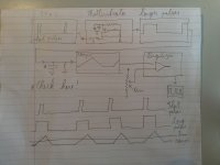
The sync signal is made of pulses, so you can't have direct adjustments, you feed it in a Monostable Multivibrator and use it to charge a small capacitor so that you have a series of small tension ramps triggered by your sync pulses, now you can use a potentiometer to set an adjustable trigger level and a comparator to digitize it for the rest of the system. This way you can introduce an adjustable delay regardless of how long the original sync signal was, you may skip the Monostable if the signal is wide enough in the beginning.
IMG_20210120_130601.jpg

Of course, this is all my fantasy, it may work in a very different way, I know nothing of CRTs. But if it works as I envisioned you may want to check the ramp capacitor.
 
Maybe the potentiometers are not good anymore. If they are quite open to see the contact, they might be dirty, dust, oxydized, maybe you can try to clean them. I did that several times successfully with contact spray and turing left right several times and then readjust. In another case I had to replace such a potentiometer by a new one of the same value and pinout to fix the issue.
 
That was my first thought--spray some contact cleaner into the pot, give the shaft a few turns. I was working with a monitor recently with similar issues and I had to disassemble a pot to get to the wiping surface. (It was one of those kit designs where you selected the resistive element, and then the shaft assembly and screwed them together.) But once cleaned, it was fine.

Most conventional potentiometers consist of a wiping contact over a carbon layer deposited on a phenolic substrate. Contacts corrode with age, the carbon flakes, dirt gets into the assembly and you get erratic operation.

Are there any Hantarex prints on this monitor? (I think that Hantarex made most of the 6300 displays).
 
Are there any Hantarex prints on this monitor? (I think that Hantarex made most of the 6300 displays).

Not the colour display of the M24, that one was made in Japan (i think by Mitsubishi). I am looking for the schematics as well. It should be part# DSM 2421C.
 
No it says Toshiba CDU 1200.

Thank for your hints! I will start with the pot because searching for a bad capacitor will be more complicated.
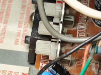
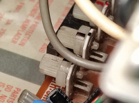
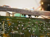
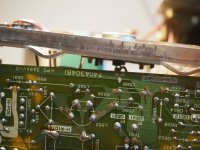
I have attached two photos of my pot. I am not sure how to disassemble it or I just need to spray it from the back? Have you encountered this type?

photo1.png photo2.png

I see some people use DeOxit D5S, bit it is something imported from USA and price goes to 40-50 dollars. But wd-40 contact cleaner is very cheap. The other popular one on our Amazon is: Facom 006064.
 
Last edited:
I use plain old CRC QD 2130 contact cleaner, but even any automotive contact cleaner should work. In the old days, the cleaner of choice would have been carbon tetrachloride, then Freon TF. Now, it's mostly a mixture of plastic-safe solvents, as nearly as I can tell. Alcohol probably wouldn't be optimal in this application because it's lousy at cutting grease and attracts water.

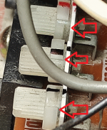
You want to get the stuff between the "knob" and the body of the potentiometer; that is, the side facing the knob. Given that the ones pictured aren't sealed units, I have no doubt that dirt plays a part in your situation.
 
Thanks. I made a picture just to verify I was able to understand in English.

photo1_pos.png
 
It is unlikely the pots problem. It is more likely that the sync signal is no getting to the multivibrator. The fact that you are able to get the adjustment to bring the horizontal to the correct value means that that part is working. Without the sync, it is expected to drift with small temperature changes.
Dwight
 
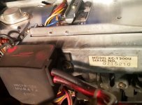
Interesting: mine is marked as DSM 2421 C on the outside and XC-1200U inside, but bought boards, the CRT etc. have Mitsubishi markings.
PC110007.JPG
 
Markings on the CRT have little to do with the manufacturer of the electronics. In the USA, for example, "Clinton" was a very common name to see on CRT labels.
 
Markings on the CRT have little to do with the manufacturer of the electronics. In the USA, for example, "Clinton" was a very common name to see on CRT labels.

But the PCBs have Mitsubishi logos too (see picture), I could try asking Toshiba if they recognize the model number.
PC110007.JPGIMG_20201209_234559 (2).jpg
 
I agree with Dwight.

What is happening when you adjust the H hold is that the picture can be made to appear normally, but it is drifting left or right and falling out of lock because it is not sync locked.

This means that the H sync pulse is not reaching the H oscillator circuit's AFC area in the monitor or if it is, the circuit that processes this pulse is defective.

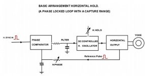
Basically the incoming H sync pulse is compared with the H scan oscillator (sometimes a multivibrator) frequency in a type of comparator circuit, this creates a error voltage that is used to adjust the H scan osc, so it falls into lock with the incoming H sync pulse. Once locked, if you adjust the H hold control, the picture will appear to move left and right. And you will get the same effect if you adjust the H phase control(H position), this merely alters the phase delay of one of the H pulses prior to the comparator, so when sync locked it will alter the horizontal position of the image on the screen.

In any case, this kind of fault requires a scope to trace the incoming H sync pulse, up to the circuit where it is compared with the H scan oscillator. Often this is a circuit using a pair of diodes (a type of comparator) called an AFC circuit (automatic frequency control) or "flywheel circuit" in vintage TV nomenclature, it produces a variable DC voltage to control the H scan oscillator frequency. It is a form of a PLL (phased locked loop) which is a negative feedback loop of sorts.

This kind of fault is pretty easy to sort out, that is if you have the schematic and a scope. Without the schematic it is "awkward" but still possible if you draw out the schematic from what you can see on the pcb.
 
I have attached a block diagram which might help make sense of my post on the topic.

In the early days of TV's and video monitors, the phase comparator was simply made from two diodes and it acted a lot like a sample hold circuit.

Later of course in TV's and modern CRT computer VDU's that circuitry got incorporated into a horizontal processor IC, which generally has in it the phase comparator, the H scan osc, the H driver circuits to drive the Horizontal scan output transistor (HOT). Connected to that IC are the components, resistors, capacitors that determine the filtering of the DC control voltage and the H oscillator's free running frequency. So you may find quite a lot of variation in the circuitry, depending on if it was built with discrete components, or done with IC's.

So if you have a VDU where it won't H lock, then you need to ensure it is being fed with the H sync pulses (of the correct amplitude, polarity and frequency) at its input connector and that the pulse is making it all the way to the H processor IC's sync input pin.
 

Attachments

  • scan.jpg
    scan.jpg
    43.7 KB · Views: 1
So it was not the pot indeed. I sprayed and I do not know how much time one needs to wait but it is the same as before.

Thank you for all the insights. Even disassembling seems difficult and I need to discharge it first.

I was thinking ... I can access the pot and the sync signal without disassembling ... so is it possible to build an external circuit that uses the sync signal and the pot signal to control the pot (electronically instead of manually)? Just an idea.
 
Back
Top