• Please review our updated Terms and Rules here

RS-232 to Current Loop Interface

glitch

Veteran Member
Joined
Feb 1, 2010
Messages
5,051
Location
Central VA
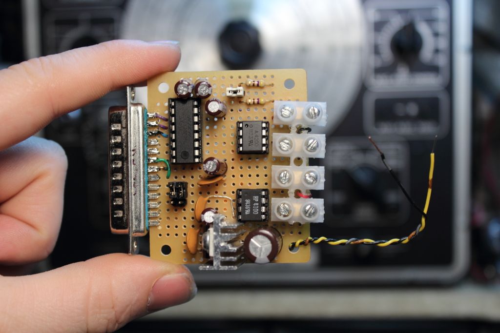
I've discussed building a vintage computer compatible current loop converter with a few of you. Since I have a little free time at work this week, I've been looking into it. Preliminary specs:

* 100% optoisolated 20 mA loop
* Proper isolated loop supply for passive devices (higher voltage than usually provided)
* MAX232 for RS-232 end
* Single +5V power supply (wall wart, +5 on aux DB25 pins, et c)
* DB25 for direct plugging into old stuff
* DOCUMENTATION!

Questions:

* How many people would be interested in a kit?
* Does anyone care about 60 mA current loop?
* What kind of current loop devices would you like documented?
* Interest in a case?
 
A USB serial to 20mA current loop would be even nicer.

DEC serial consoles used to connect to an ASR33 TTY. The serial console interface has the normal 20mA in/out for the TTY, and it had an additional 20mA for the reader run magnet for the paper tape reader. We connect the reader run signal to the RS-232 CTS signal so it can be used for flow control.
 
I'm planning on a speed converter as well, for using old 110 baud interfaces with devices that don't go down to 110 baud (USB converters, et c.)

I hacked a simple one together which has been tested and working with an Intel Intellec 4 MOD 40 (and 8 MOD 80) from an Arduino, a couple of optoisolators and resistors, and a hacked version of the software serial library to get down to 110 baud. It works, though!

Kyle
 
With the help of a few people here to debug an issue or two, I have an optoisolated adapter that works amazingly well.

rs232cv.gif

CGS_0633.jpg

CGS_0634.jpg


Not seen on the schematic was a jumper to add or remove local power to the loop, and two more jumpers that I could use to to make the adapter operate as a loopback for the computer or current loop, plus as a crossover so you would never need a null modem cable.
It's very small and a great candidate for having proper PCB's etched. It also cost approximately $25 to build (The optoisolators were $10 each, the MAX232 was basically $2 and the other odds and ends were $3)
 
That's pretty close to the design I have laid out, except I'm using a transformer-isolated switchmode supply for the loop current, and taking regulated 5V input from either pins 9+10 of the DB25 (this is a sort-of standard) or a micro USB receptacle (so you can use a cheap, common cell phone charger). My design uses 4N33 darlington optoisolators because that's what I had in my components supply, and they're cheap.

My loop supply is also jumper/switch selectable, since some of my equipment is active, some is passive, and some is active on one side while passive on the other!
 
Since MIDI is basically a current-loop interface, I wonder if one could modify a (cheap Chinese) USB-to-MIDI adapter to create a USB-to-TTY adapter from one?

In the old days, one could take an IBM Async adapter card, set if for current loop interface and change the crystal and end up with a cheap MIDI adapter for the PC.
 
* How many people would be interested in a kit?
* Does anyone care about 60 mA current loop?
* What kind of current loop devices would you like documented?

I'd be very interested in a 60 mA version, since I've got an old Creed 7E laying around.
Sign me up! :D
 
Board layout in progress! I'm going to double the receive/transmit loops for full reader run control, plus it'll make use of those other two tranceivers on the MAX232.
 
Just an update, we're in the process of moving and a job change. I should have time to wrap this up after the move. Sample parts ordered!
 
Prototype PCBs ordered from OSH Park! I was able to keep nearly everything through hole, except the isolation transformer. This is a large SMD part and should be extremely easy for anyone to solder. Prototypes are 3x4" boards, double-sided, with DB25F on one end and large screw terminals on the other. Provides: TX, RX, reader run, AUX current loop input, isolated 12V loop supply, proper level shifting via MAX232, status indicators for all four lines. Rendered topside image:

 
Prototype boards are in, and I've assembled one: it "mostly works!" There were a couple of schematic errors, which were easily corrected (permanently and in testing). I also misunderstood how the switchmode transformer driver I'd chosen drives transformers: instead of a 12V loop supply capable of 4x 20mA loops, I ended up with a 24V supply capable of only driving 2x 20ma loops. My "easy substitution" option is to use a transformer wound to produce a 10V loop supply. The other option would be doubling the number of supplies, or finding a different driver/transformer pairing.

I think the 10V loop supply is the better option for the majority of people. While higher loop supply might be better in some cases, it's probably not really relevant to the average case in which the loop is not physically long. Thoughts?
 
Well, the 10V supply didn't work out, so I decided to go ahead and modularize the current loop send/receive circuits and the power supply. This will end up providing a 24V loop voltage (for passive loops, like teletypes). I'm also going to include a constant current source/sink so that there's no having to pick resistors based on expected loop voltage. The modules will be in a hobbyist/breadboard friendly format, so if anyone wants to include really solid TTL -> 20 mA current loop drivers, they don't have to build their own.

Question: the circuitry I'm currently working with has an effective max working voltage of 30 - 40 VDC, depending on the optocouplers used. This should be more than adequate for pretty much all active loops out there. There's a possibility of destroying the converter if you happen to connect something higher voltage or turn on the built-in current source on an active loop. I can include a relay-based loop cutout circuit with "Loop Overvoltage" indicator if that would be helpful. Including it would make the board larger, but anyone who didn't want that functionality (it'd add a small cost, of course) could jumper over it. Worthwhile?
 
Laid out the isolated power supply module today:

power_module.jpg

It's off to OSH Park. Connector samples came in, too.
 
Sample boards in! The 24V isolated loop supply module works fine, and I think switching to a modular design was a good idea. Here's pictures of the supply plugged in to a test fixture:

vJOMH6r.jpg


vmF520c.jpg


DUJyTMy.jpg
 
Another design question:

Dissipation for the current source is OK with 24V loop supply and a 2N3906 through-hole transistor. It will be out-of-spec at the max allowable loop voltage (40V) and could/would damage the 2N3906. I can do a few things:

1. Use a different through-hole transistor, like the 2N2907, and require a heatsink at higher loop voltages
2. Use a big TO-220 power PNP
3. Use a surface-mount 2N3906
4. Lay down multiple transistor footprints for desired power level
5. Make different modules for low/high power level
6. Try and redesign the current source

I like options #1 and #3 the best. #4 and #5 reduce the minimal configuration design goal. #2 makes the module larger, which is OK but not ideal. #6 sucks because I like my current design and it's cheap! Thoughts?
 
Back
Top